Process flow diagram
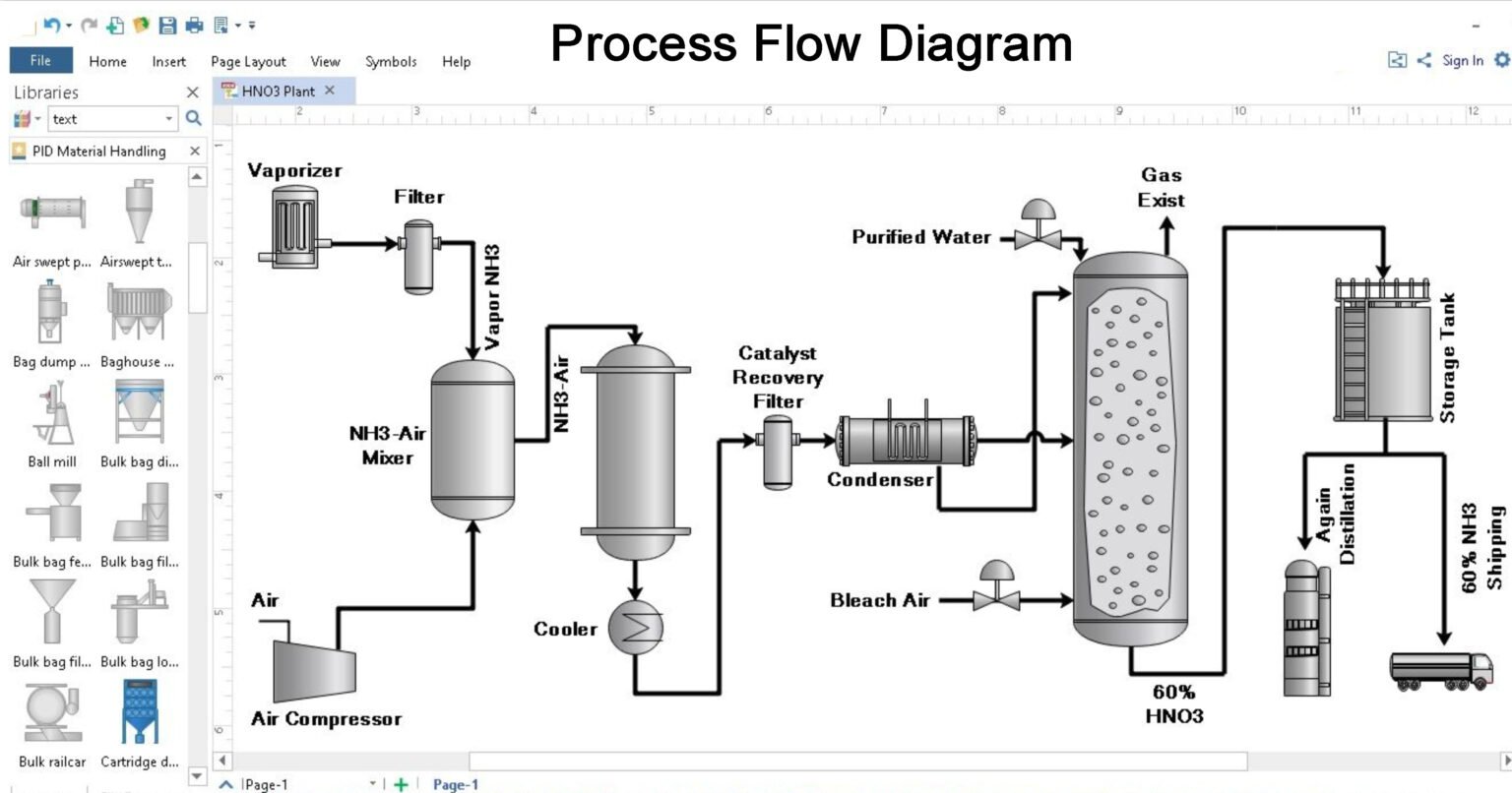
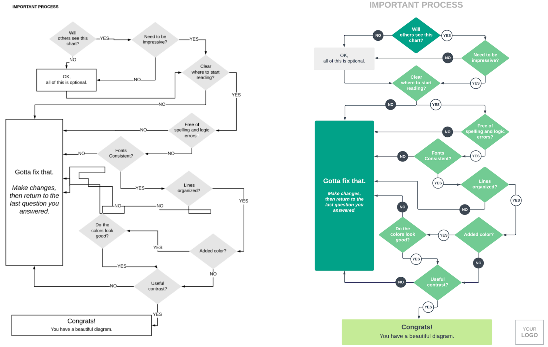
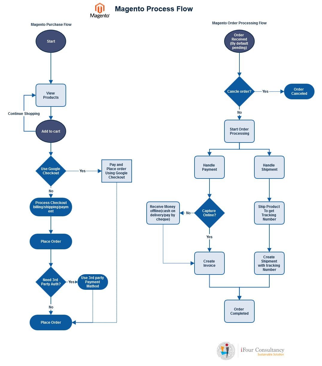
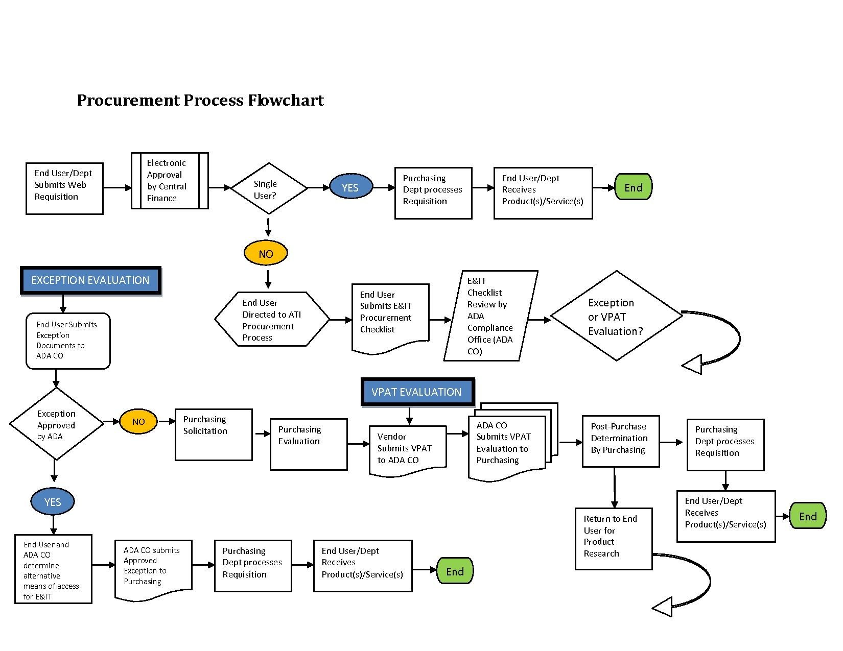
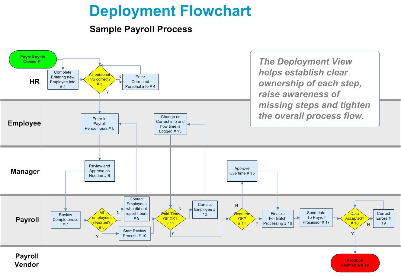
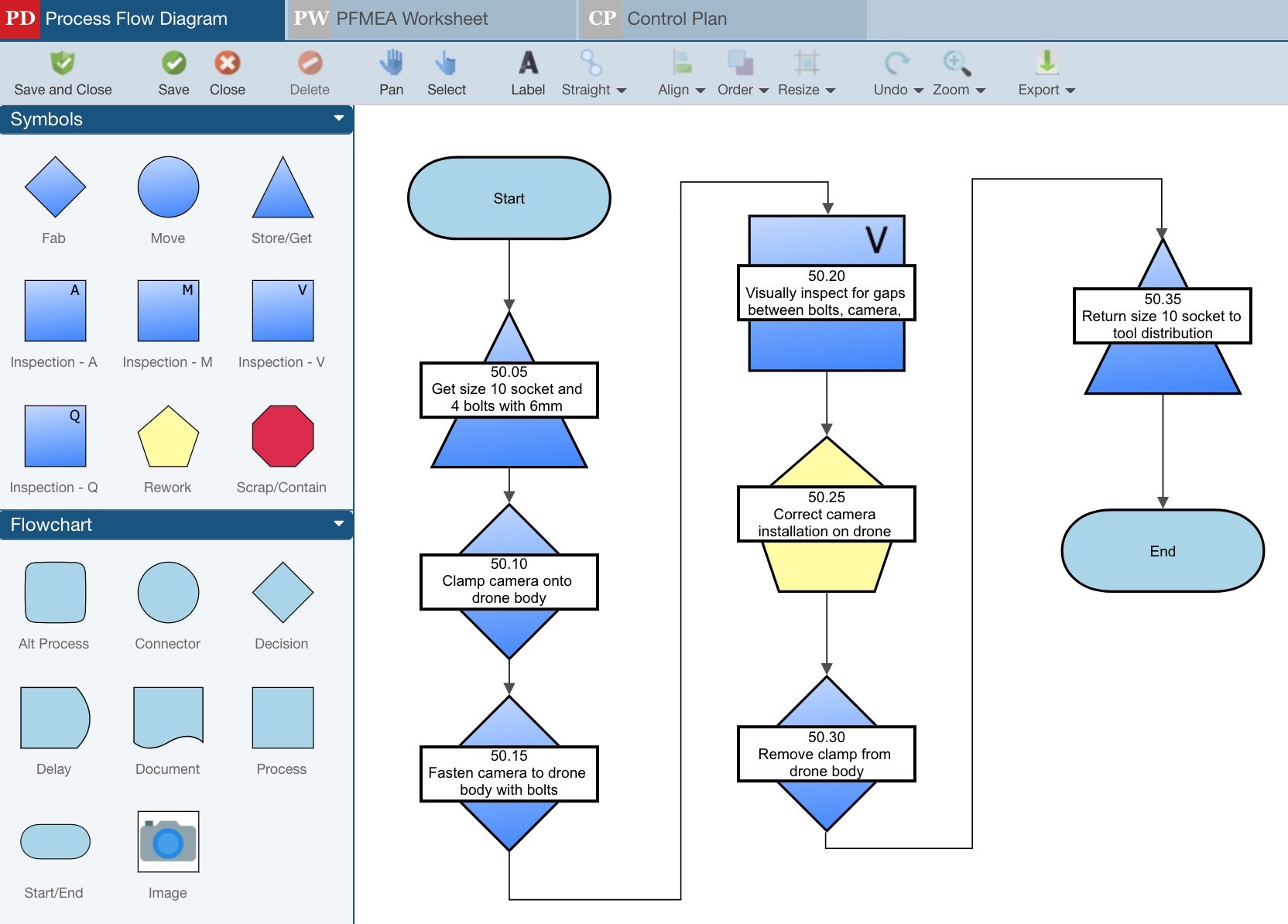
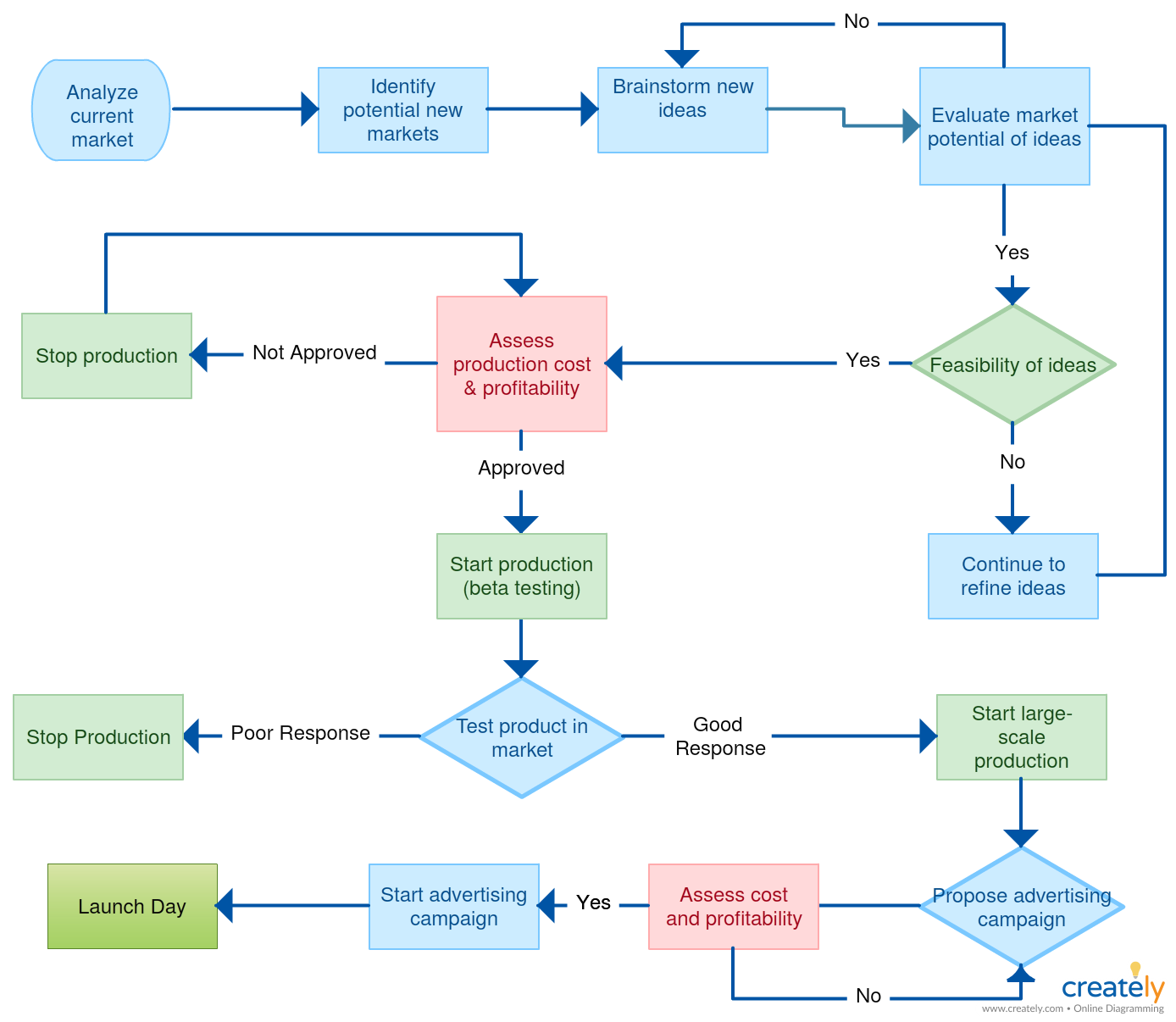
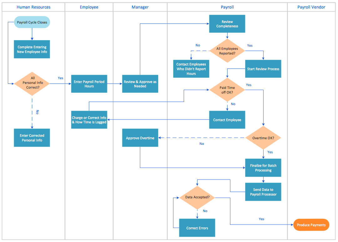
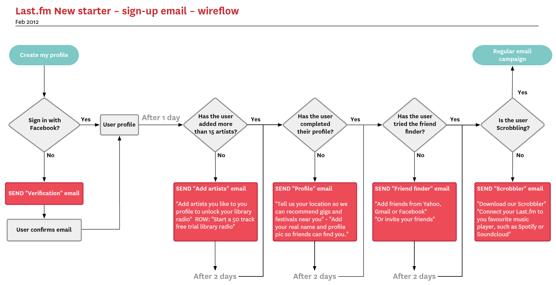
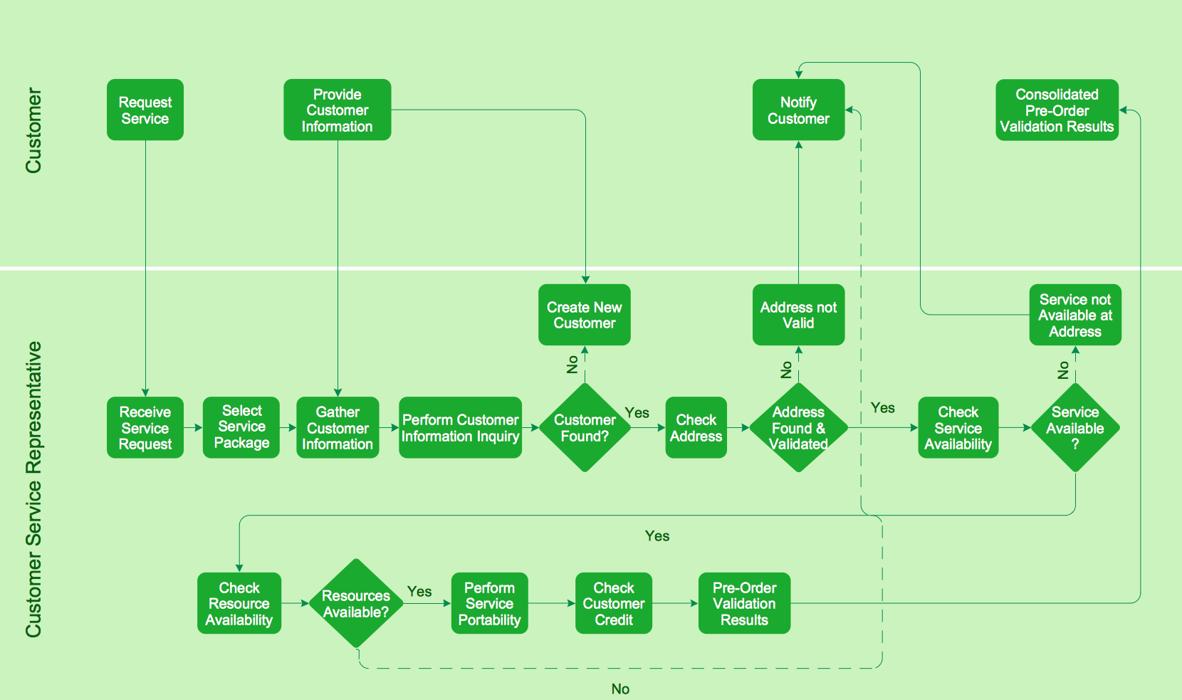
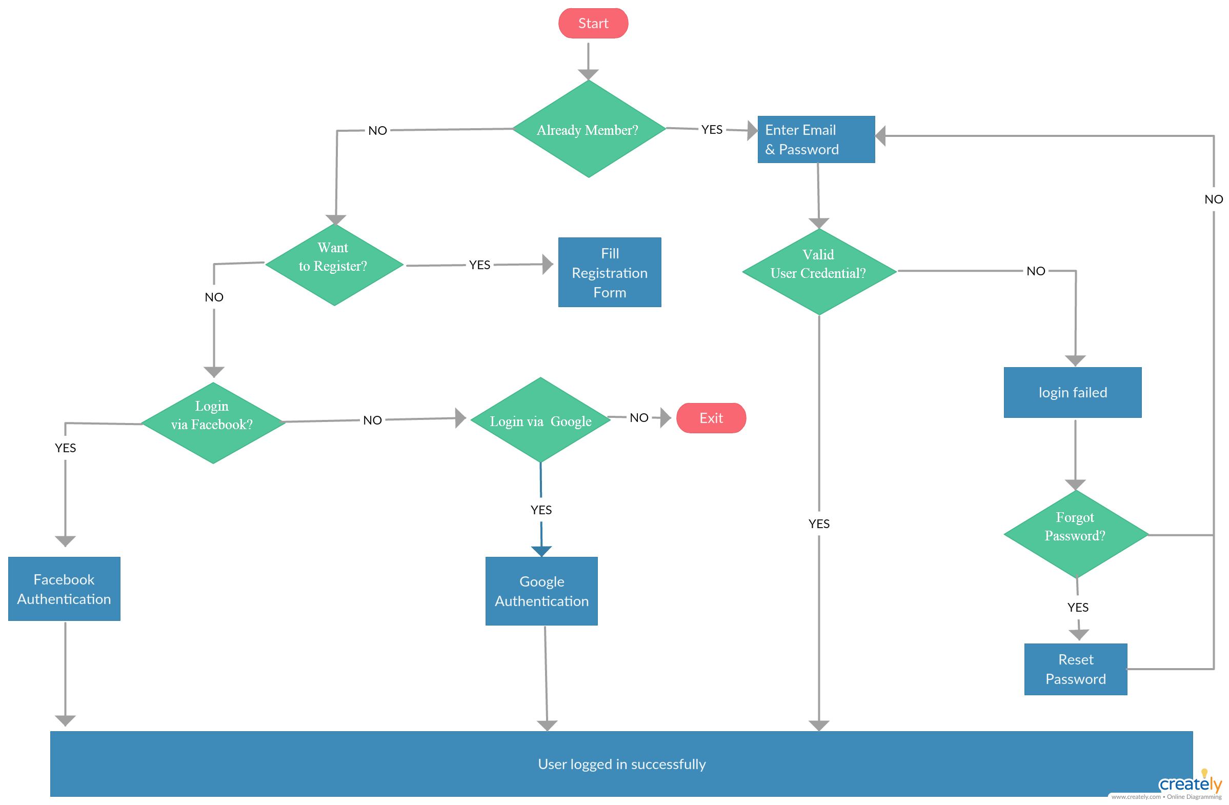
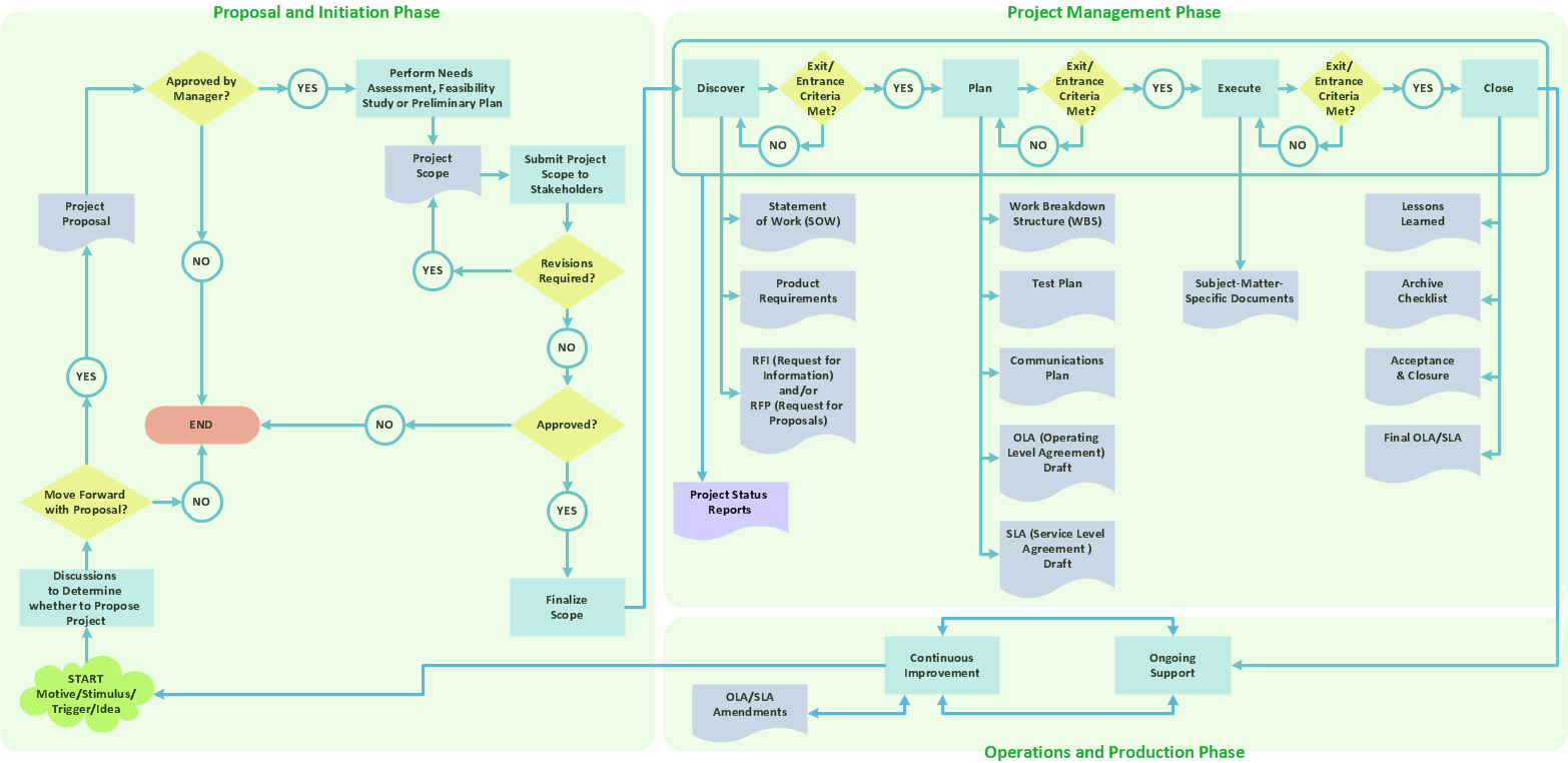
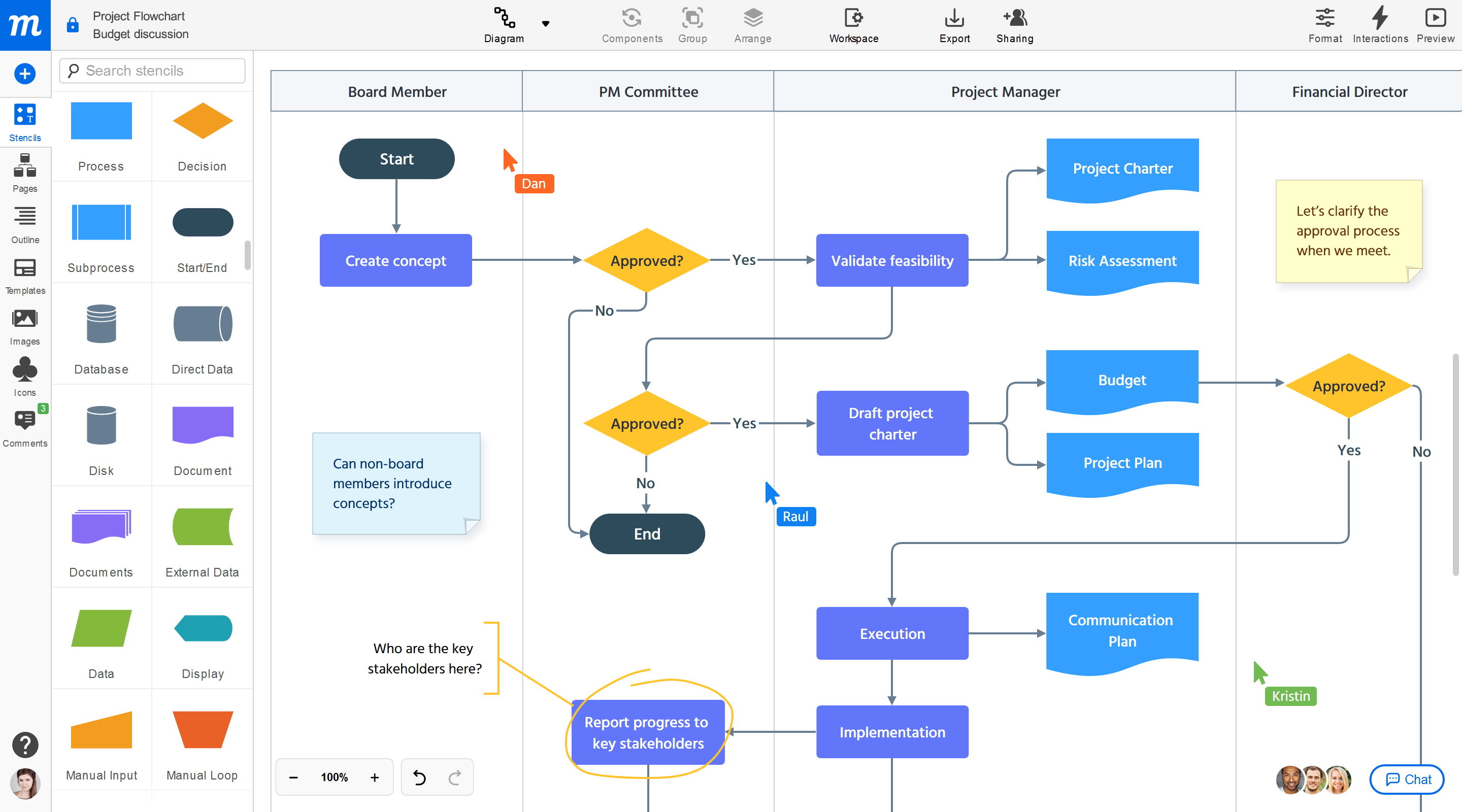
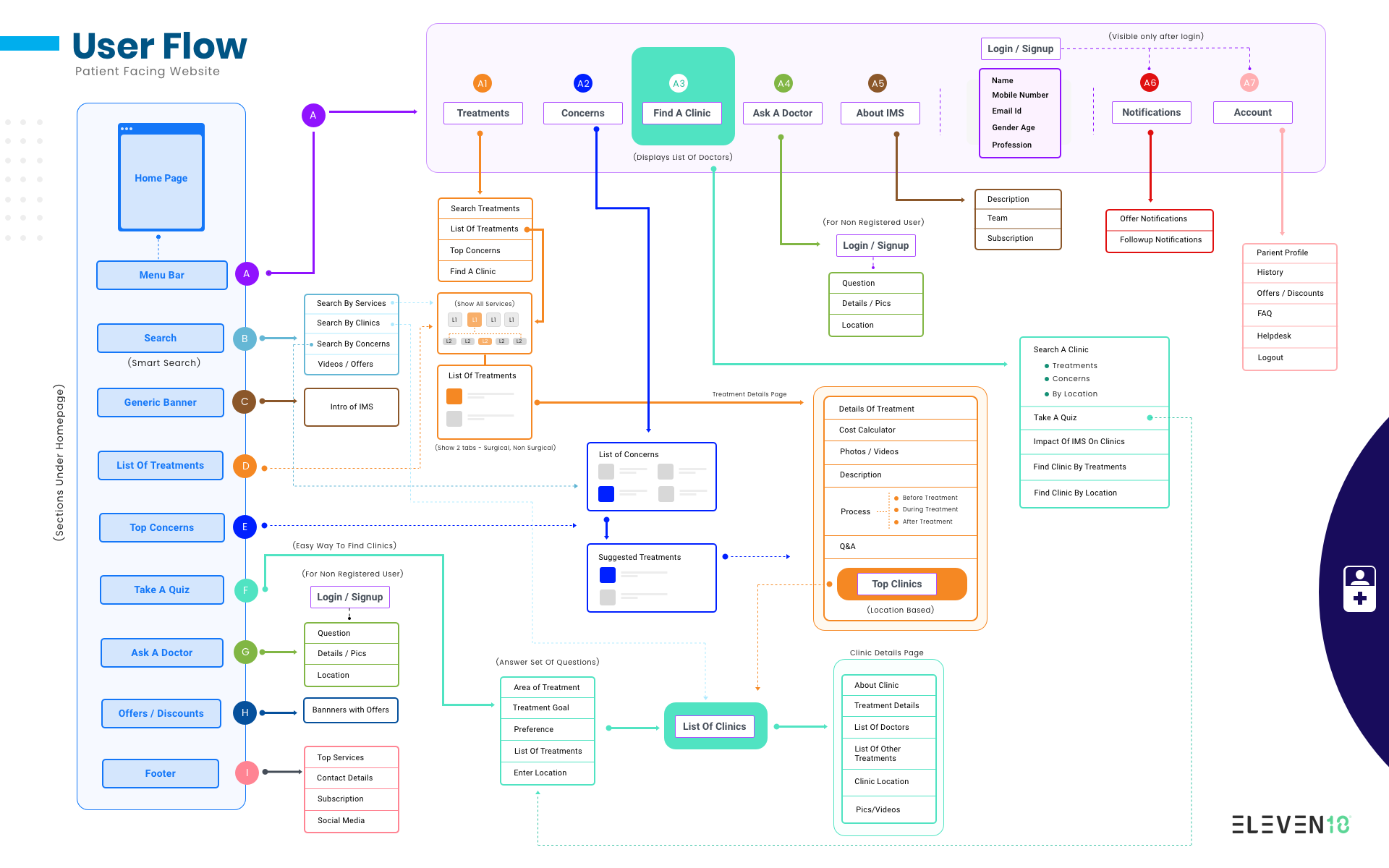
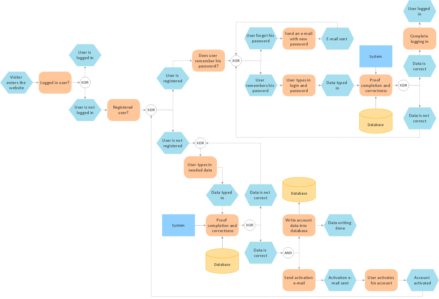
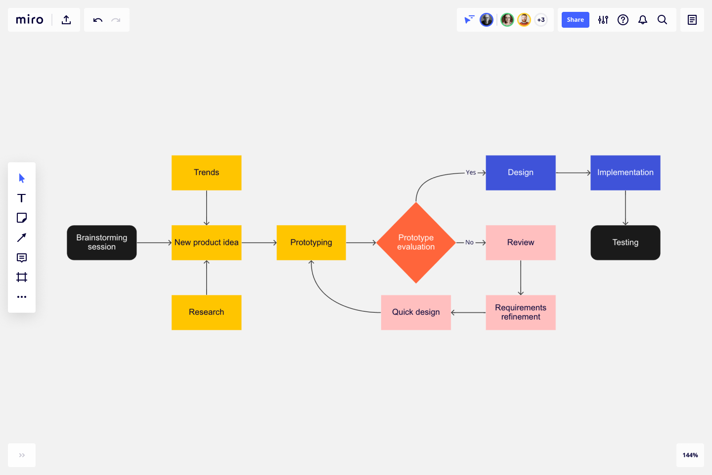
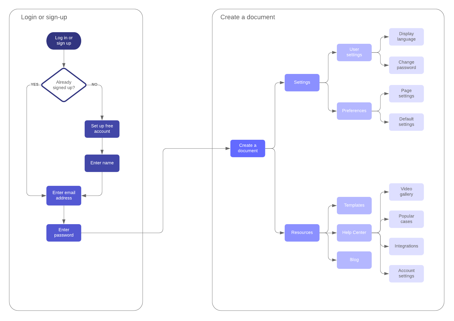
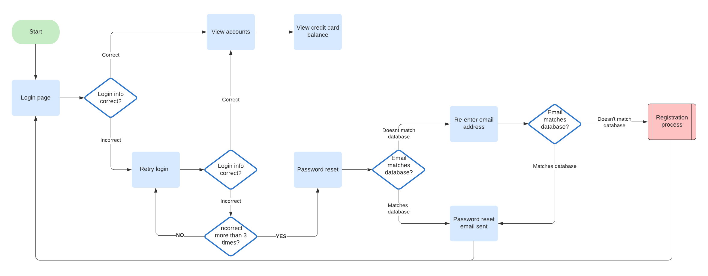
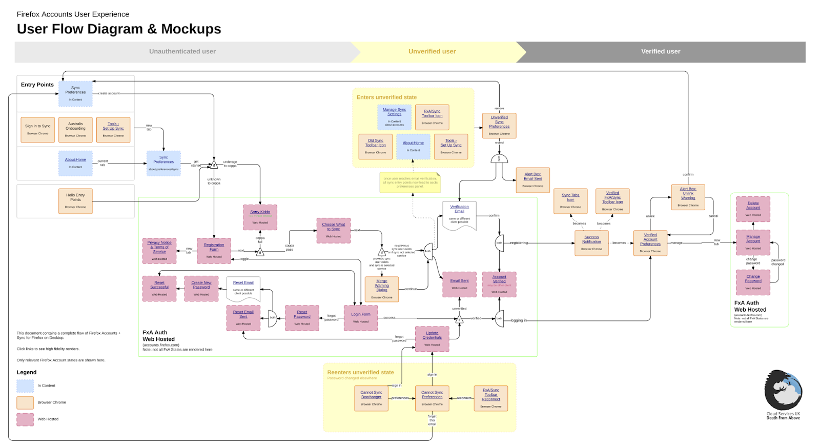
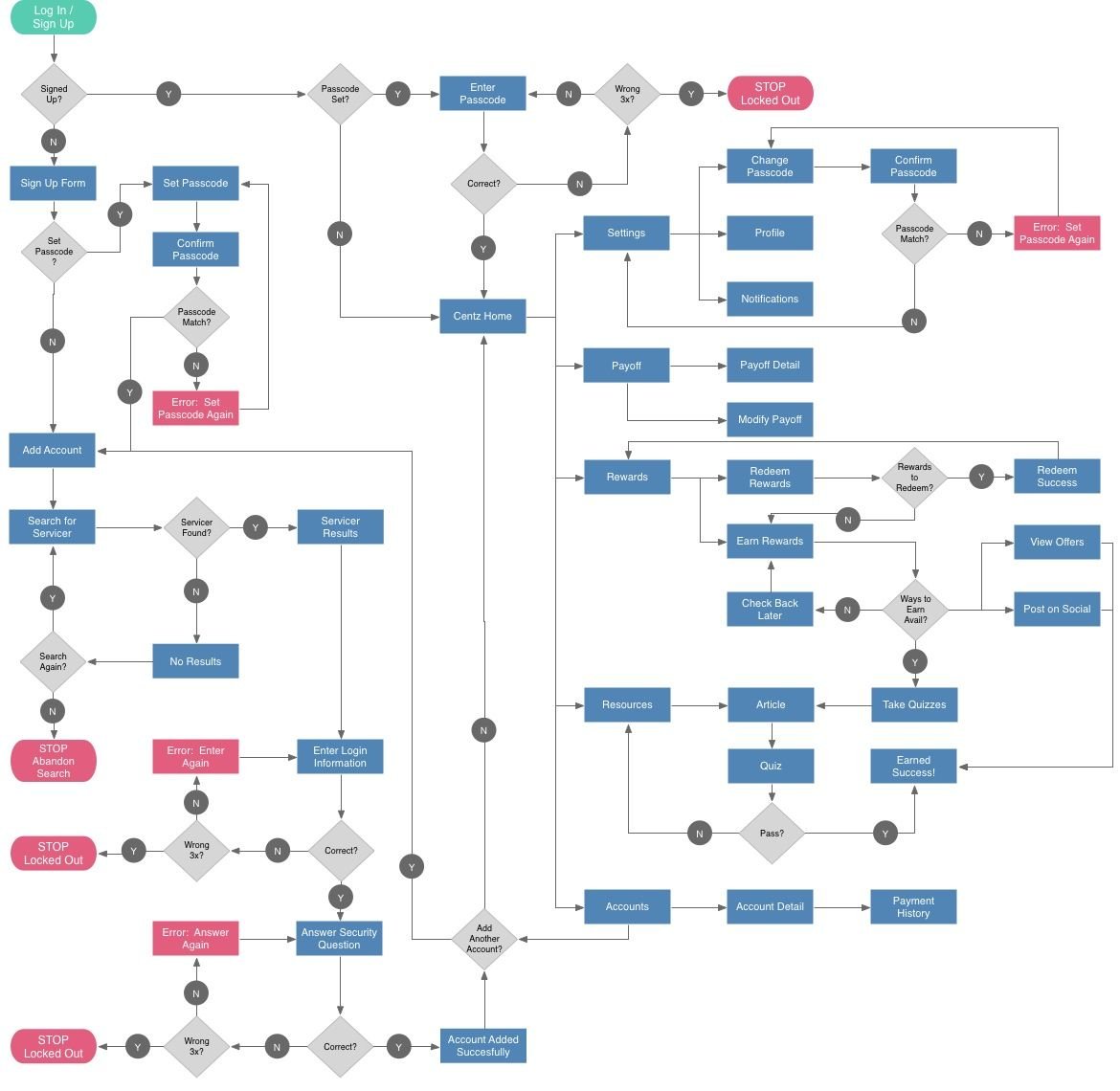
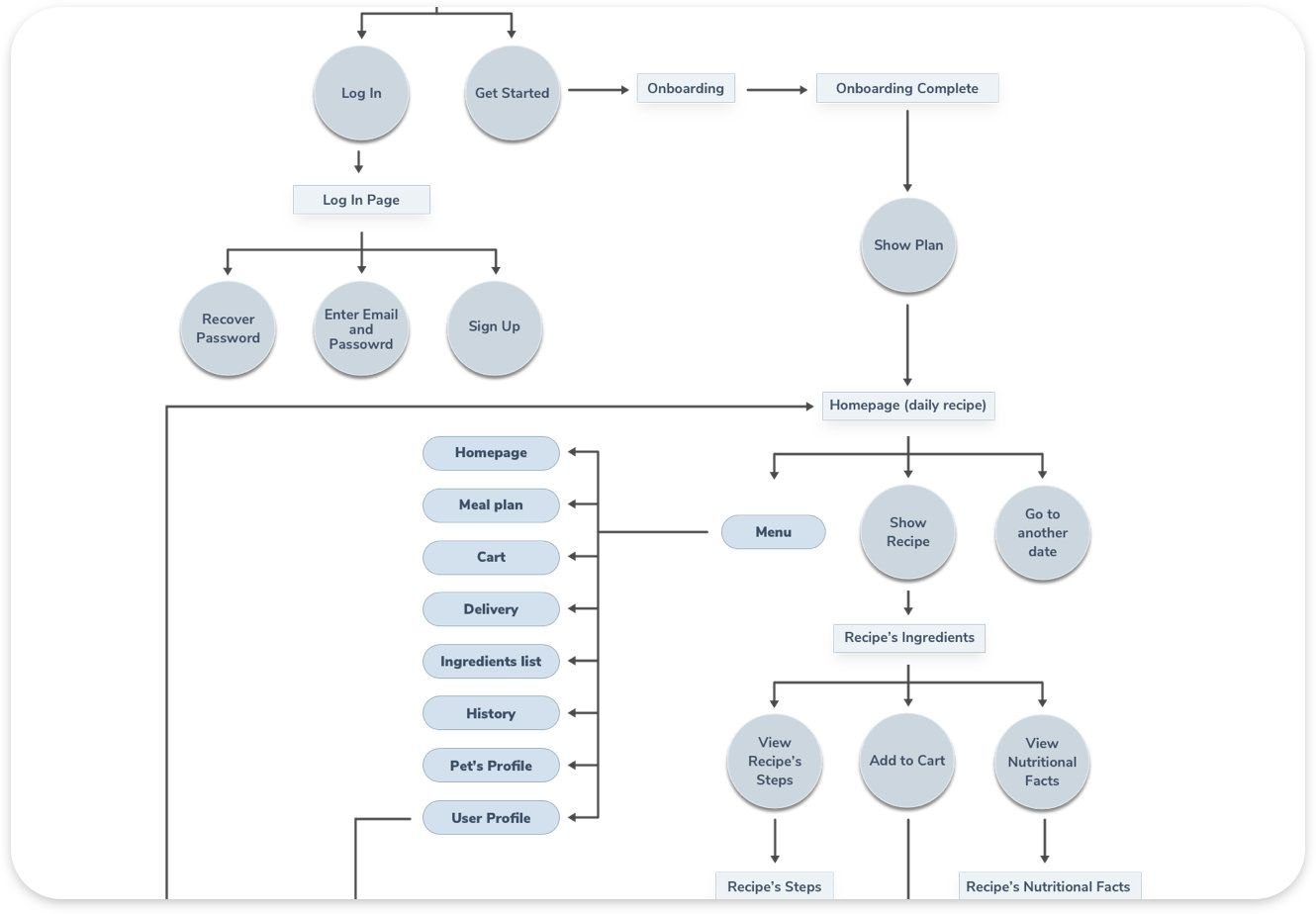
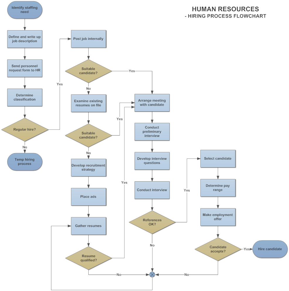
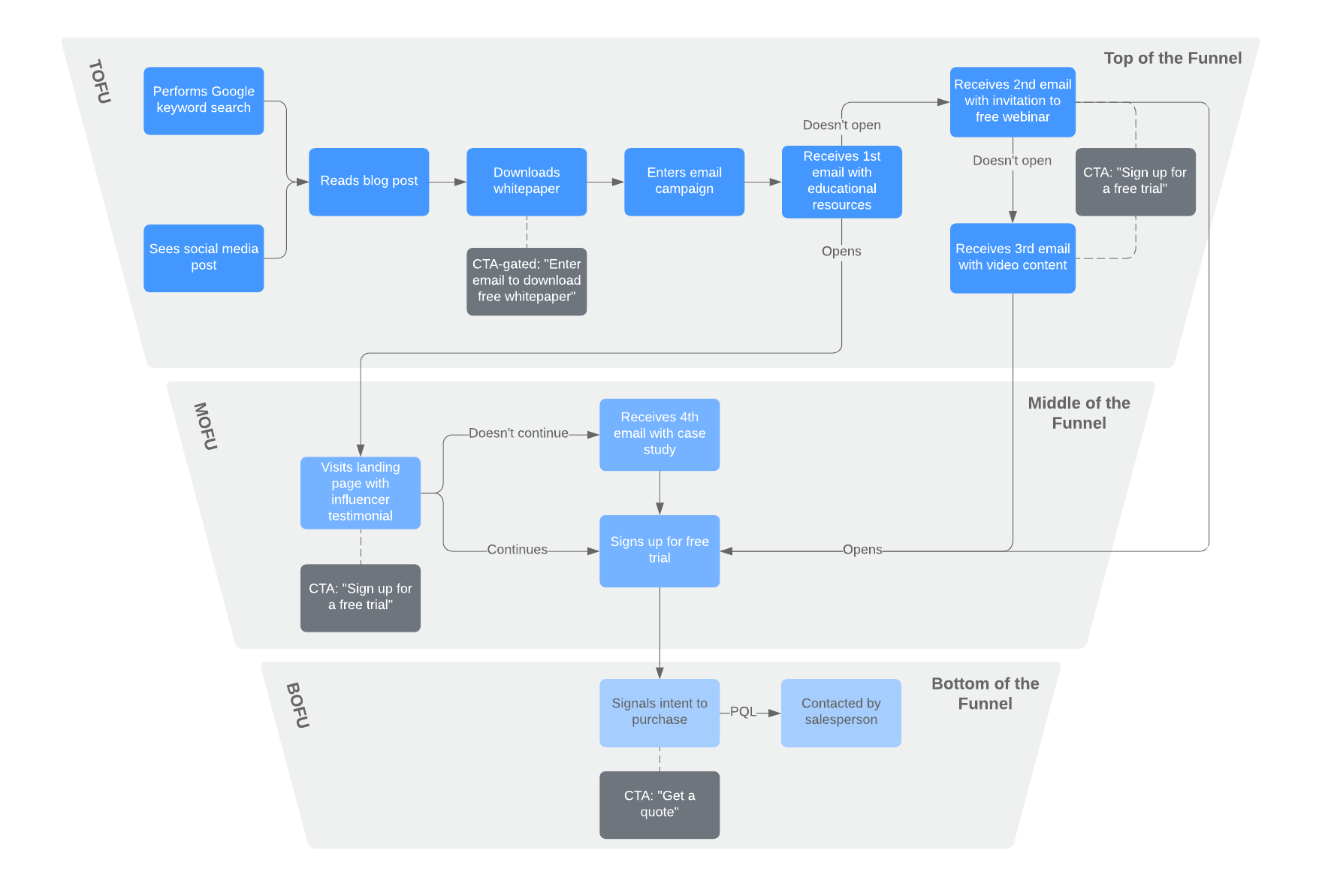
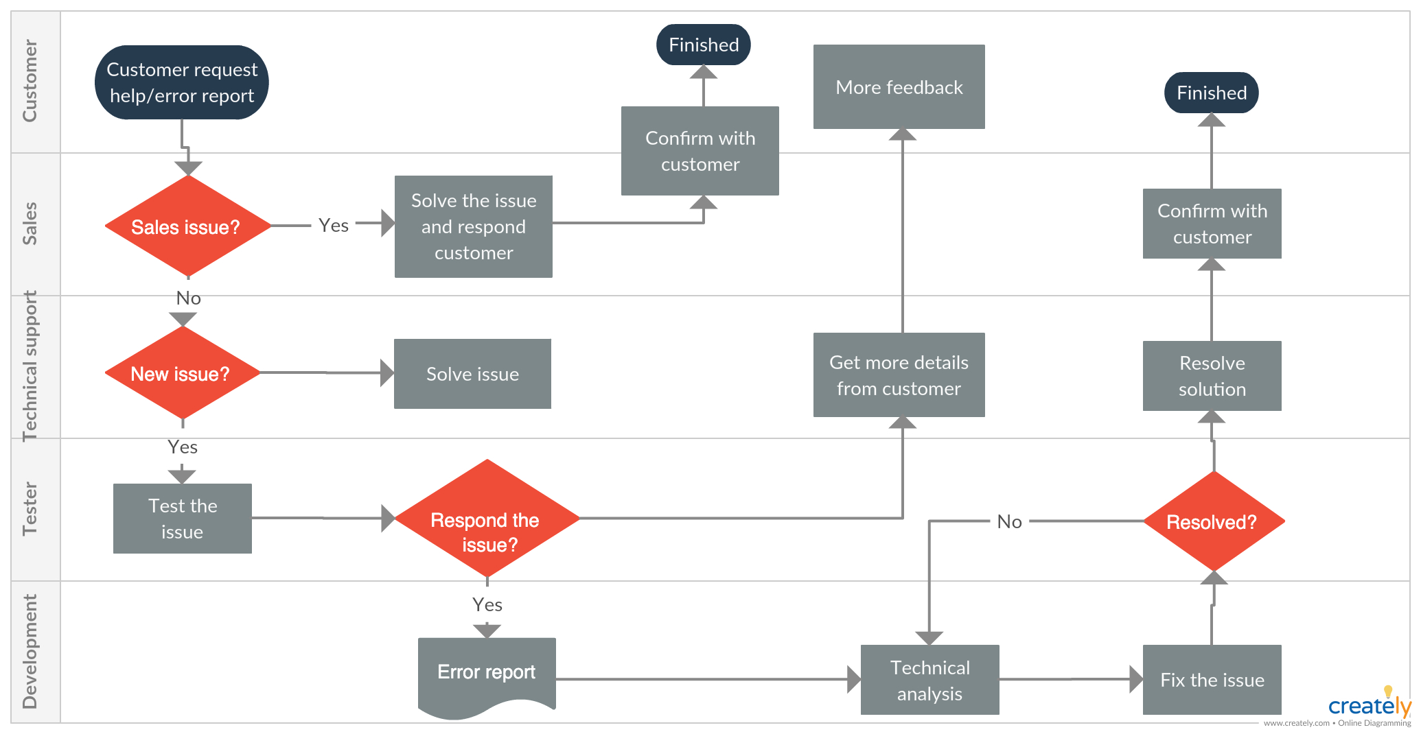
A process flow diagram (PFD) is a visual representation of the sequence of steps involved in a process or system. It provides a clear and concise overview, highlighting the interconnections between different stages. PFDs are widely used in various industries, including manufacturing, engineering, and project management, to map out workflows and identify potential bottlenecks.
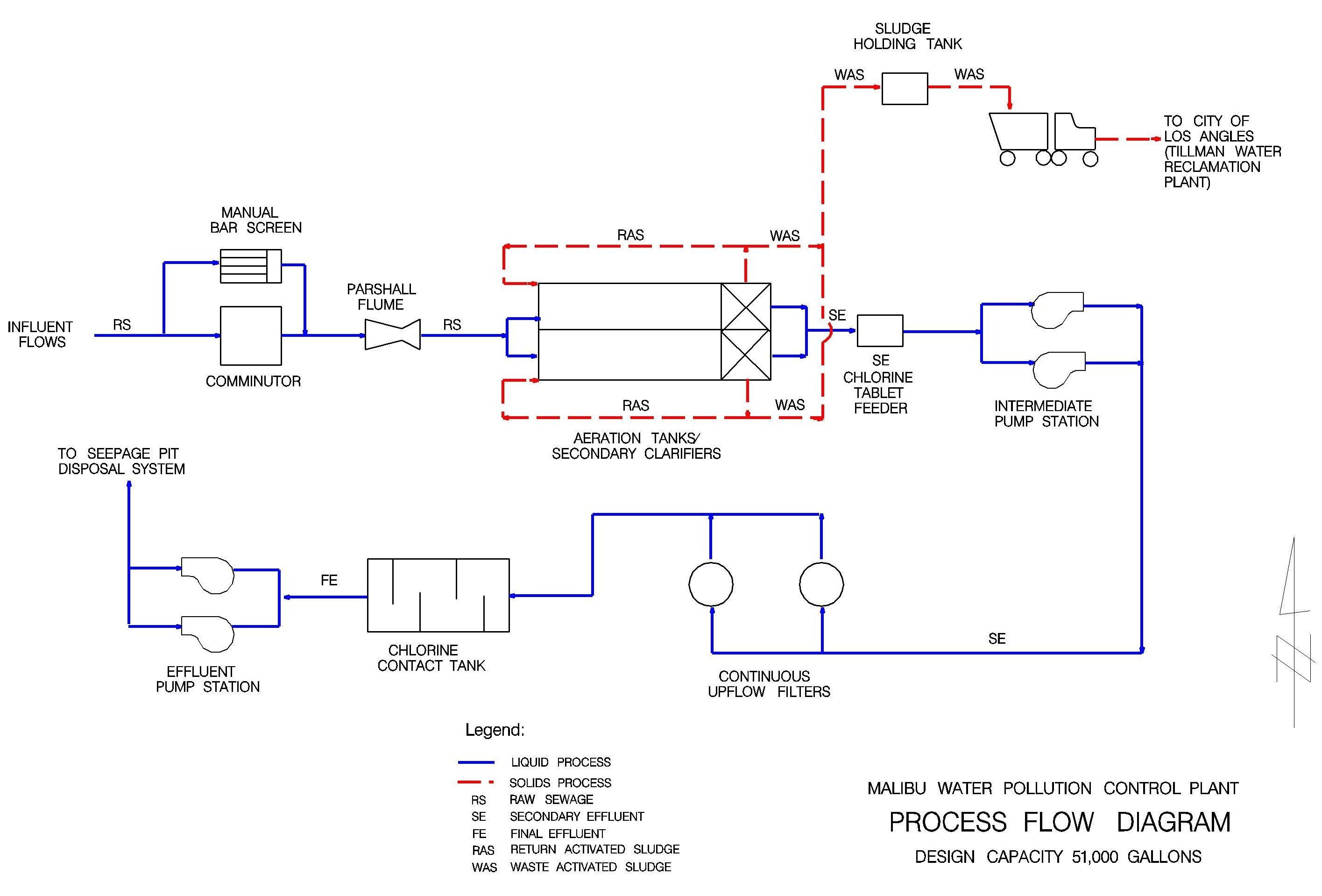
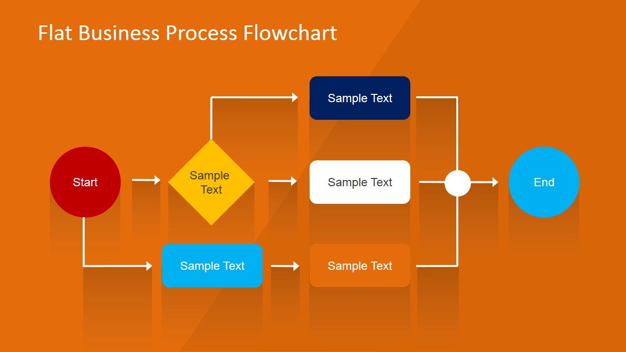
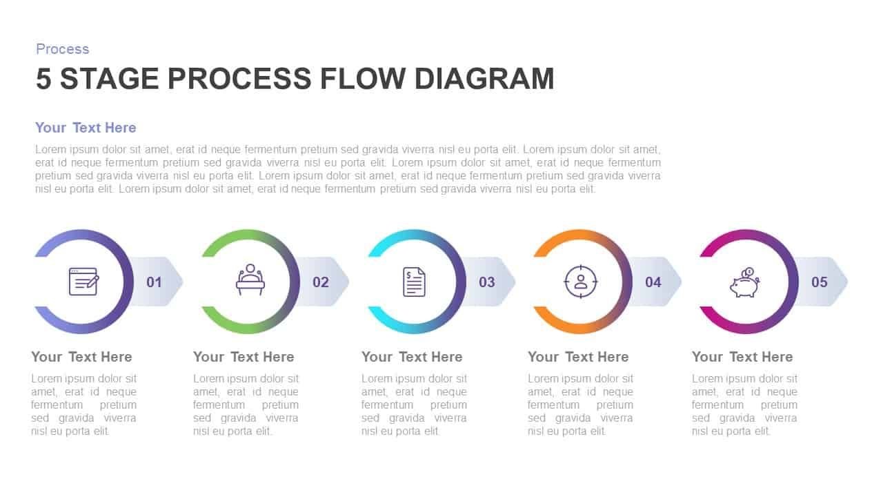
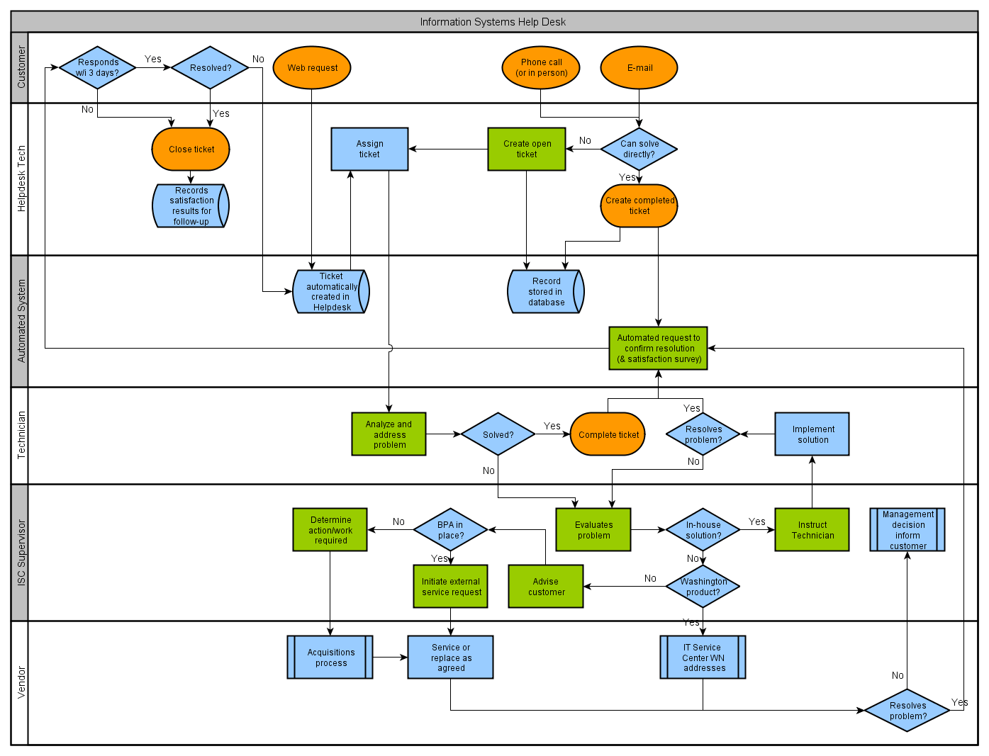
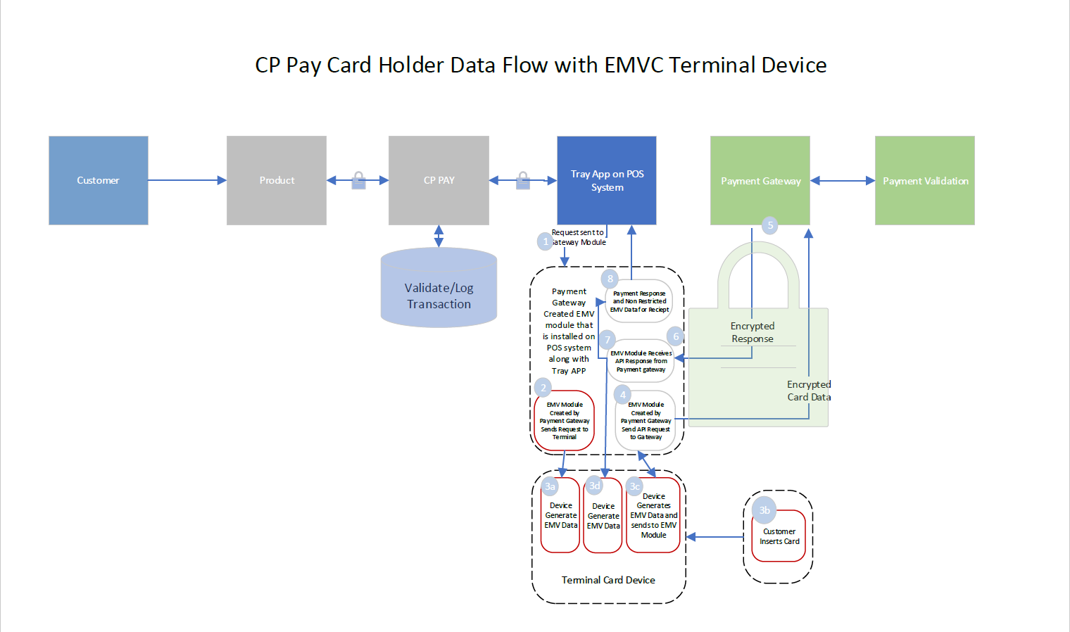
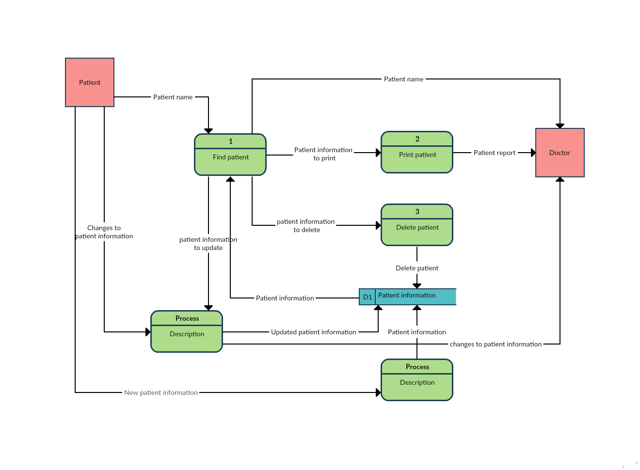
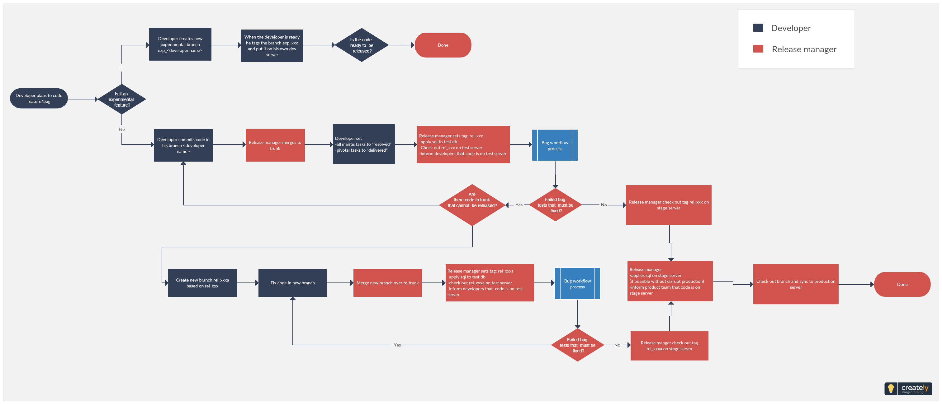
The purpose of a PFD is to simplify complex processes by breaking them down into manageable units. It showcases the flow of materials, energy, and information, allowing stakeholders to understand the overall structure and functionality of a system. By presenting this information visually, a PFD facilitates effective communication and collaboration among team members.
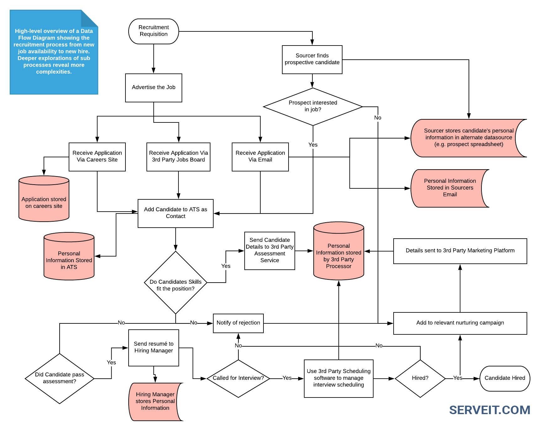
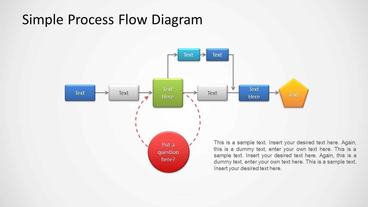
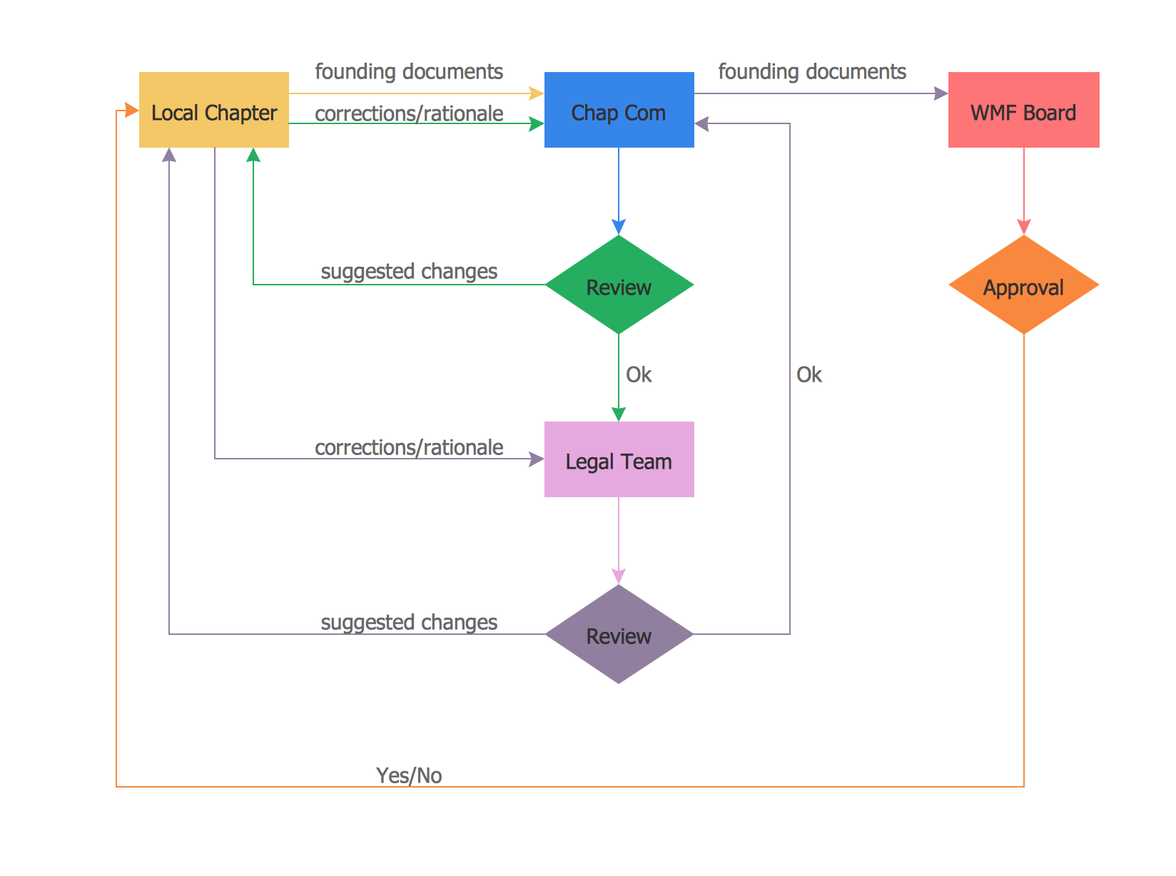
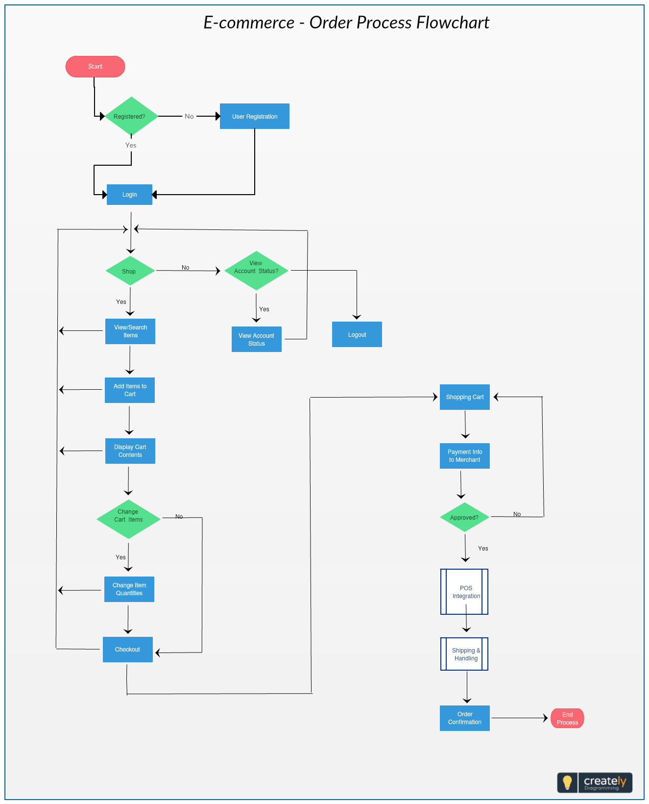
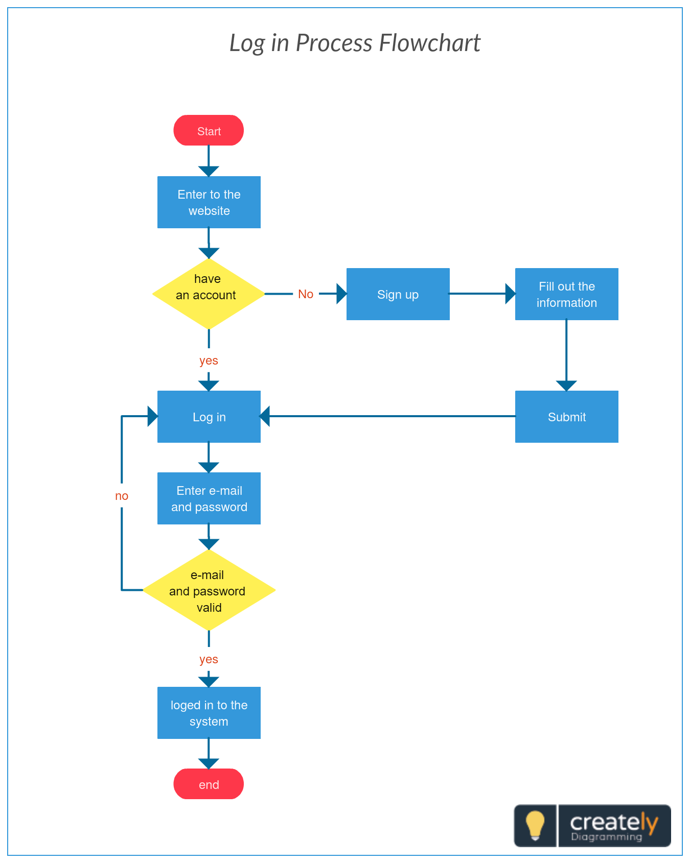
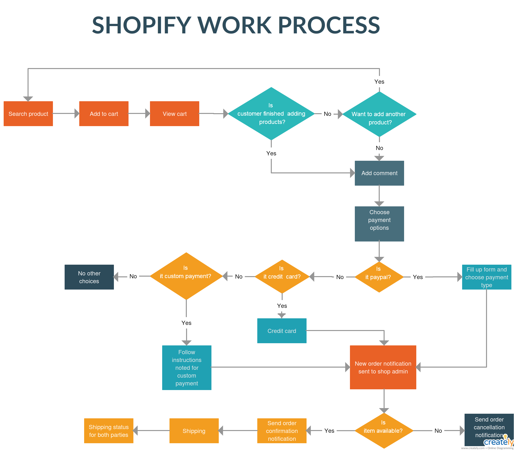
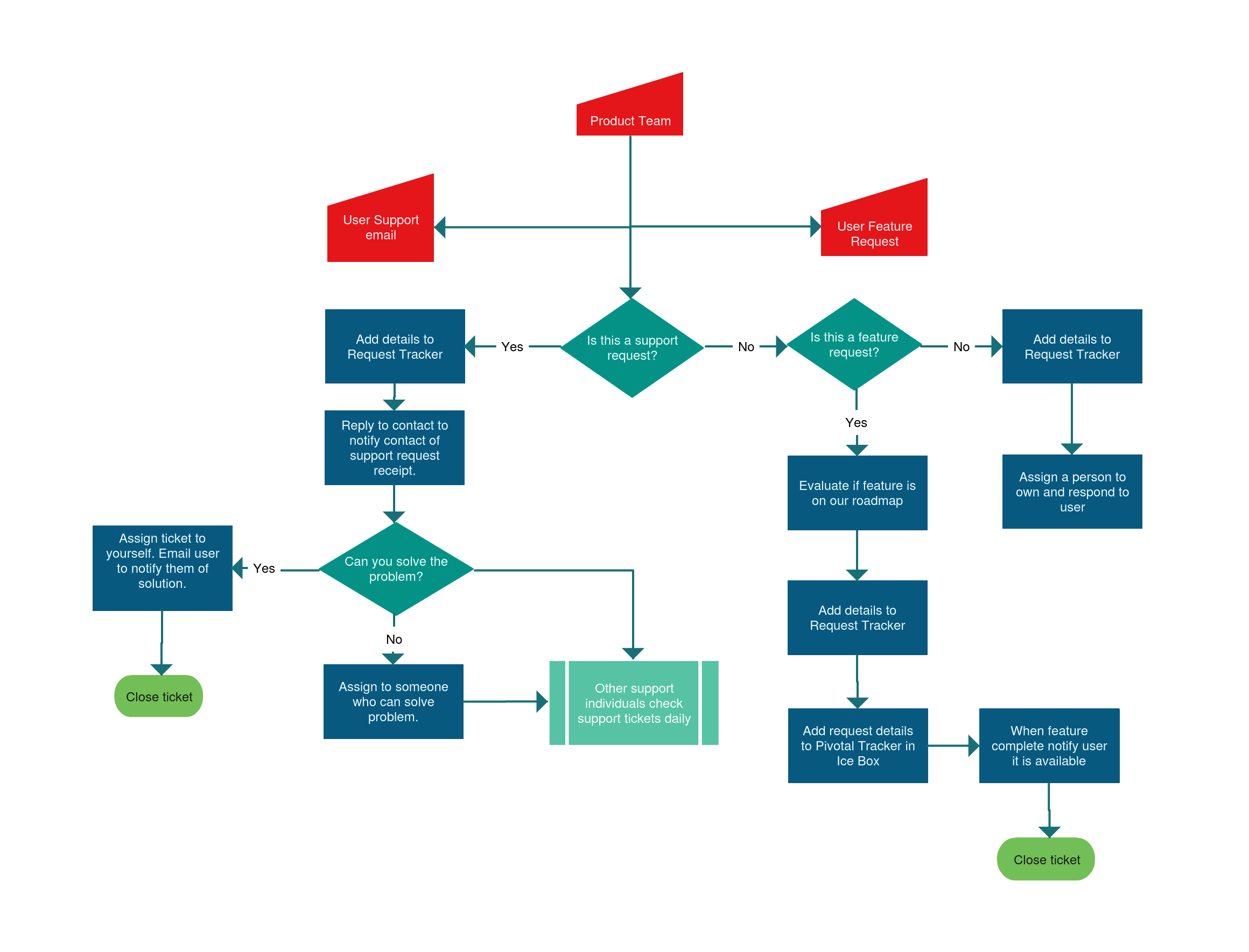
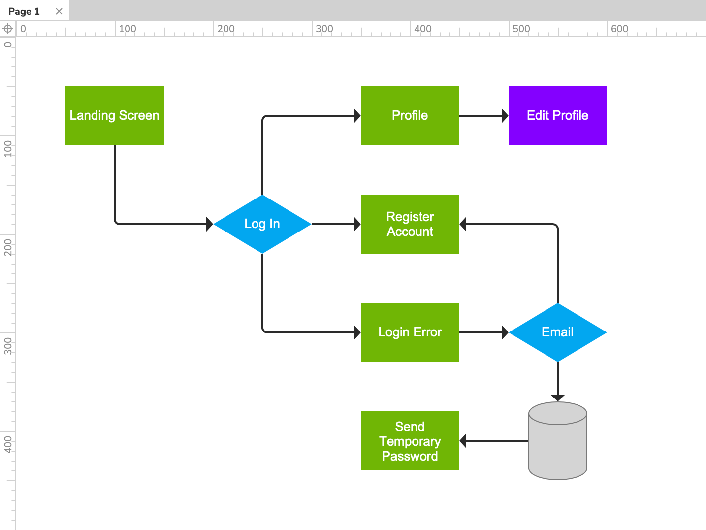
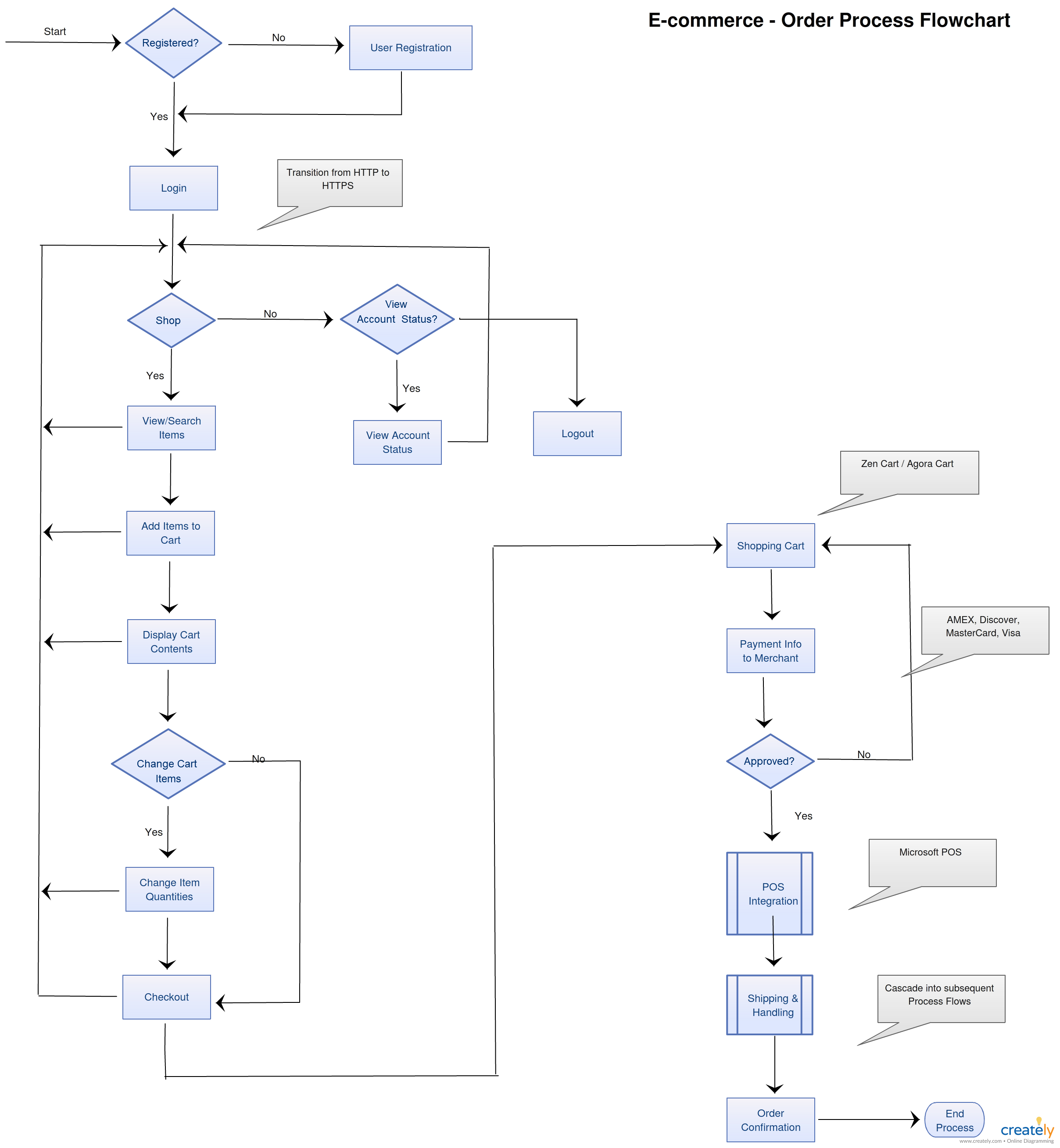
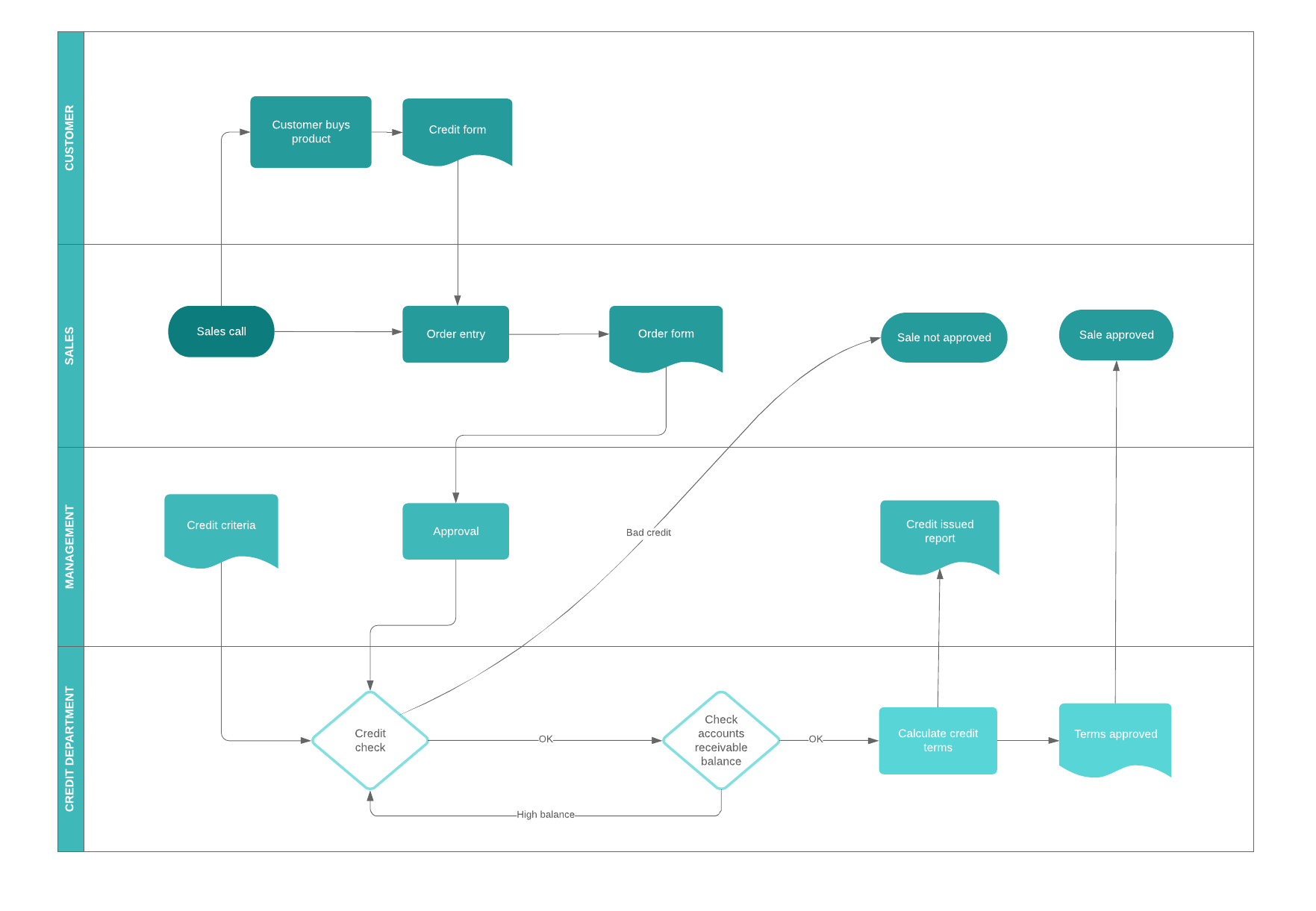
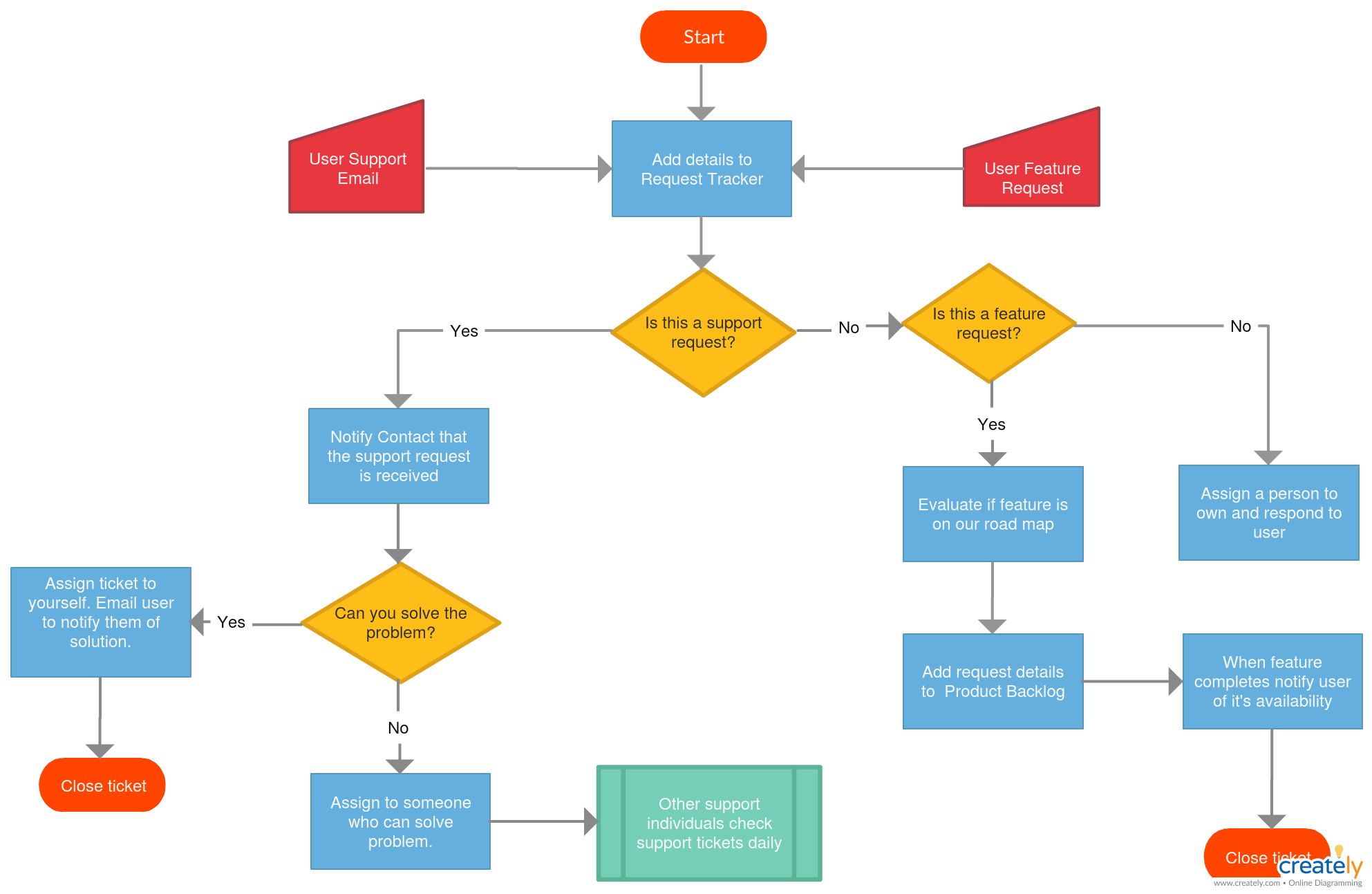
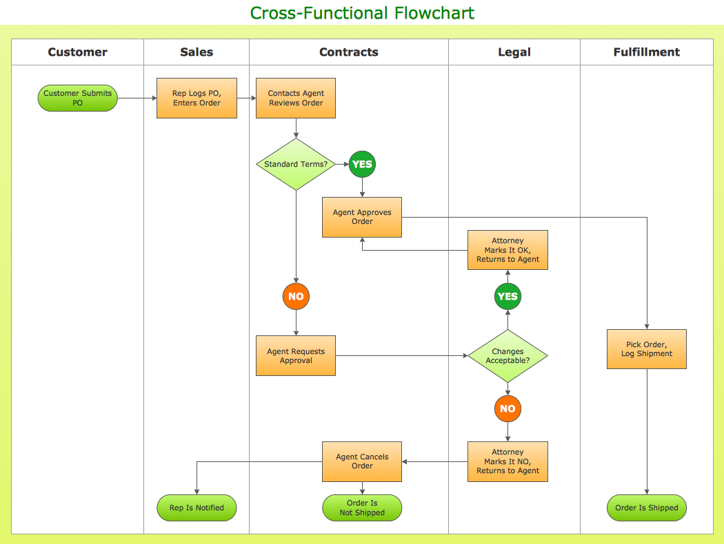
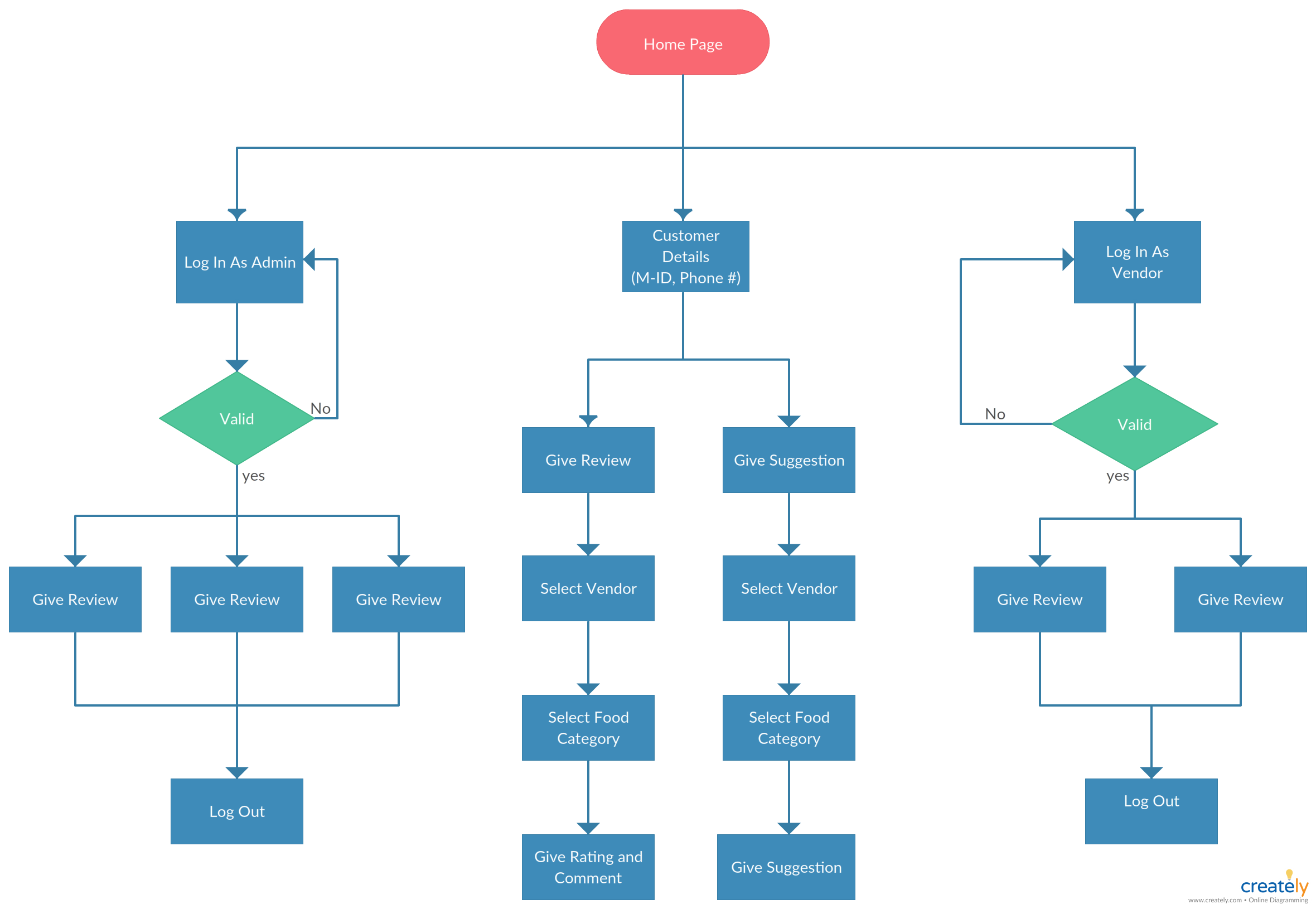
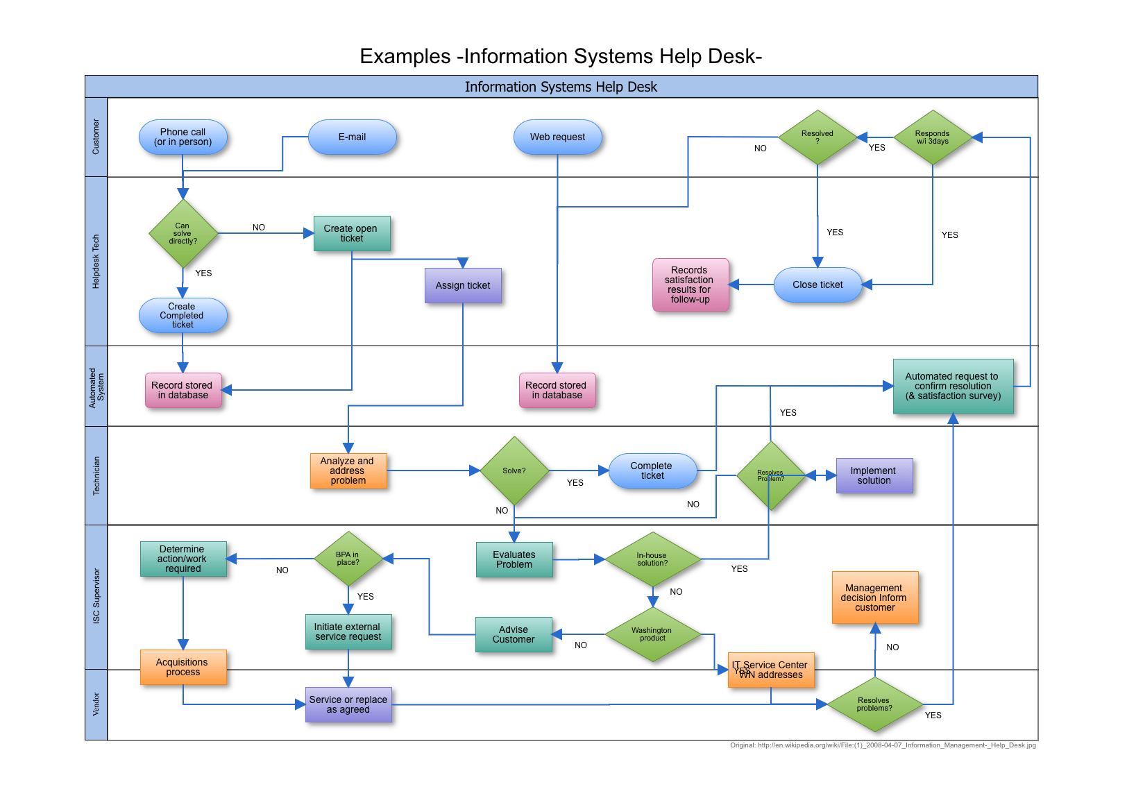
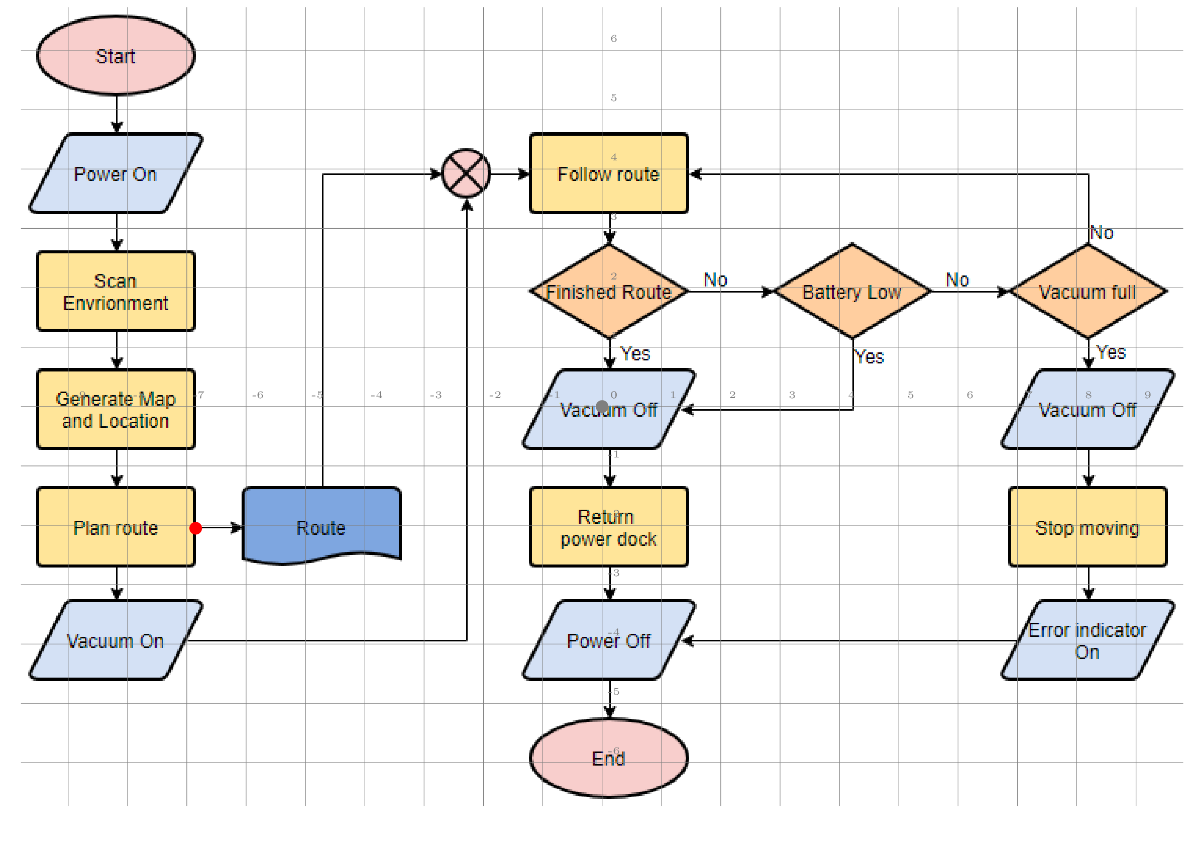
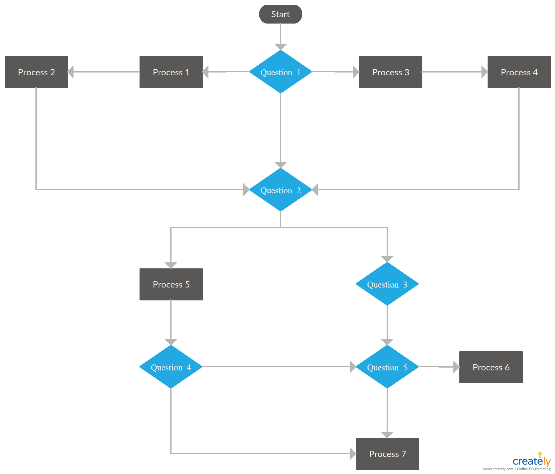
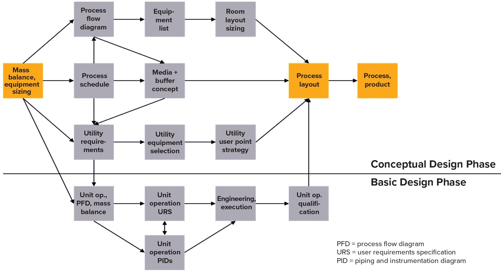
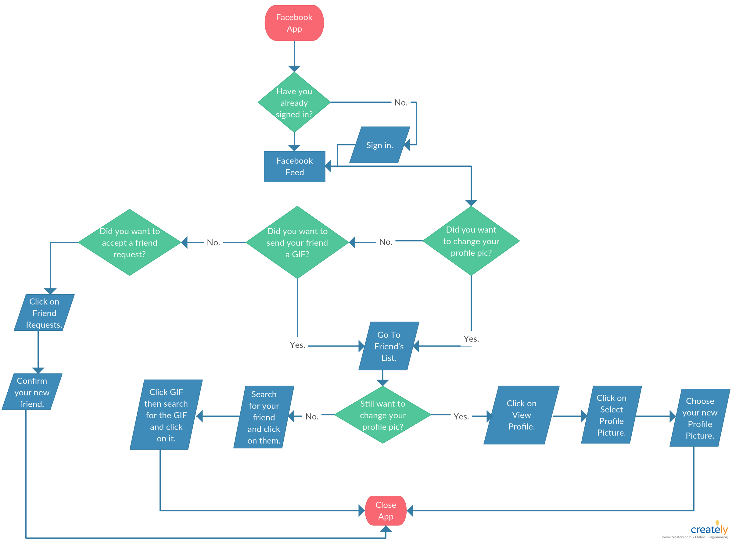
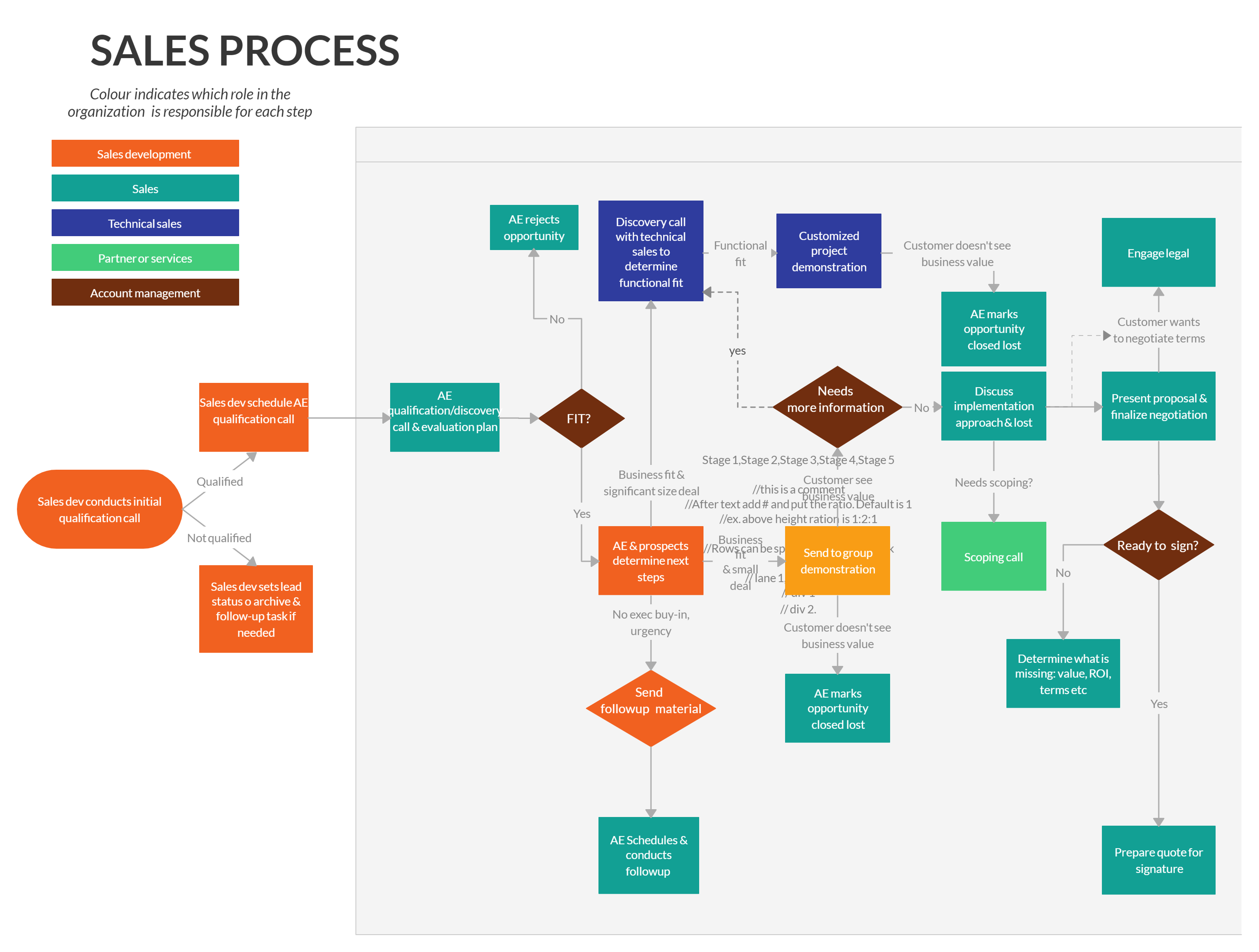
Typically, a PFD consists of symbols and lines representing different elements of the process. Symbols can represent equipment, such as pumps, valves, or reactors, while lines illustrate the movement of materials or the transfer of energy. Arrows and labels indicate the direction and nature of the flow, ensuring clarity and understanding.
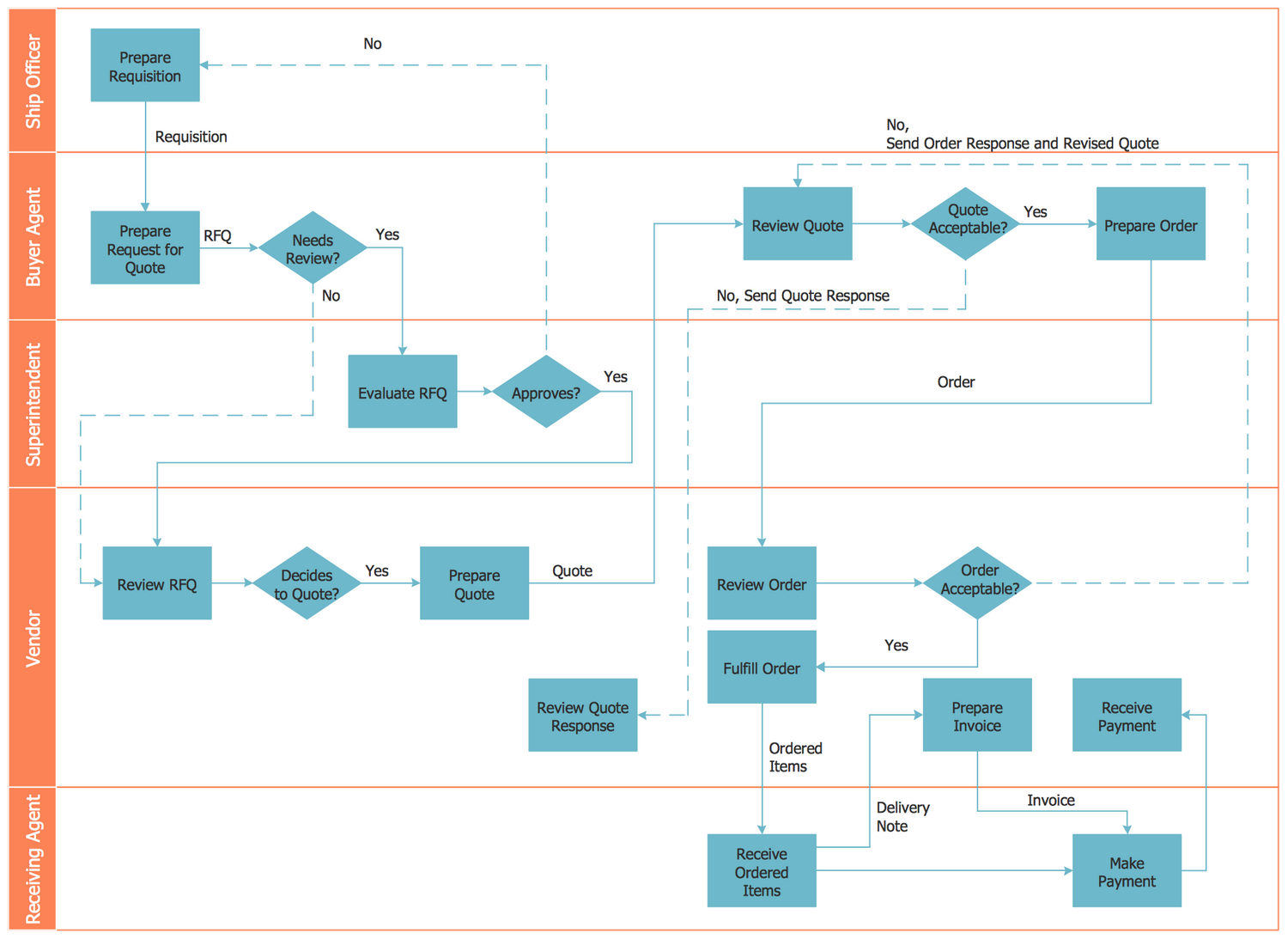
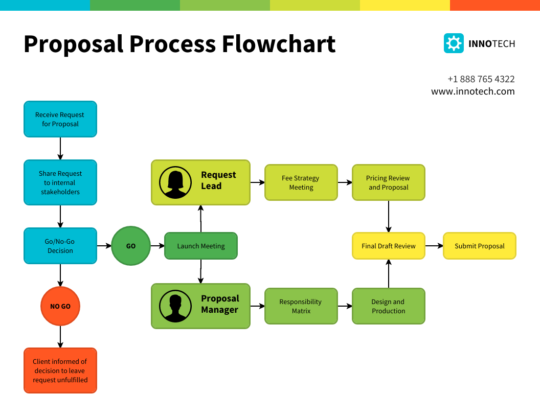
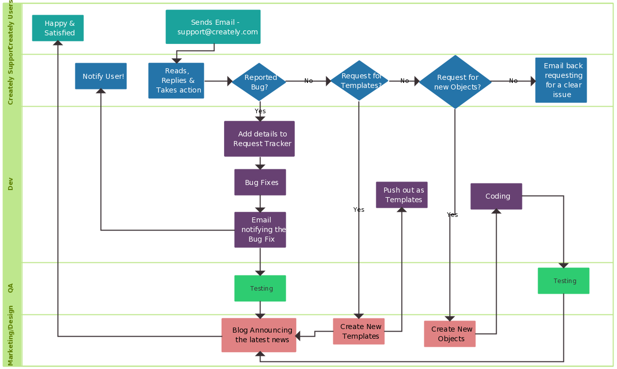
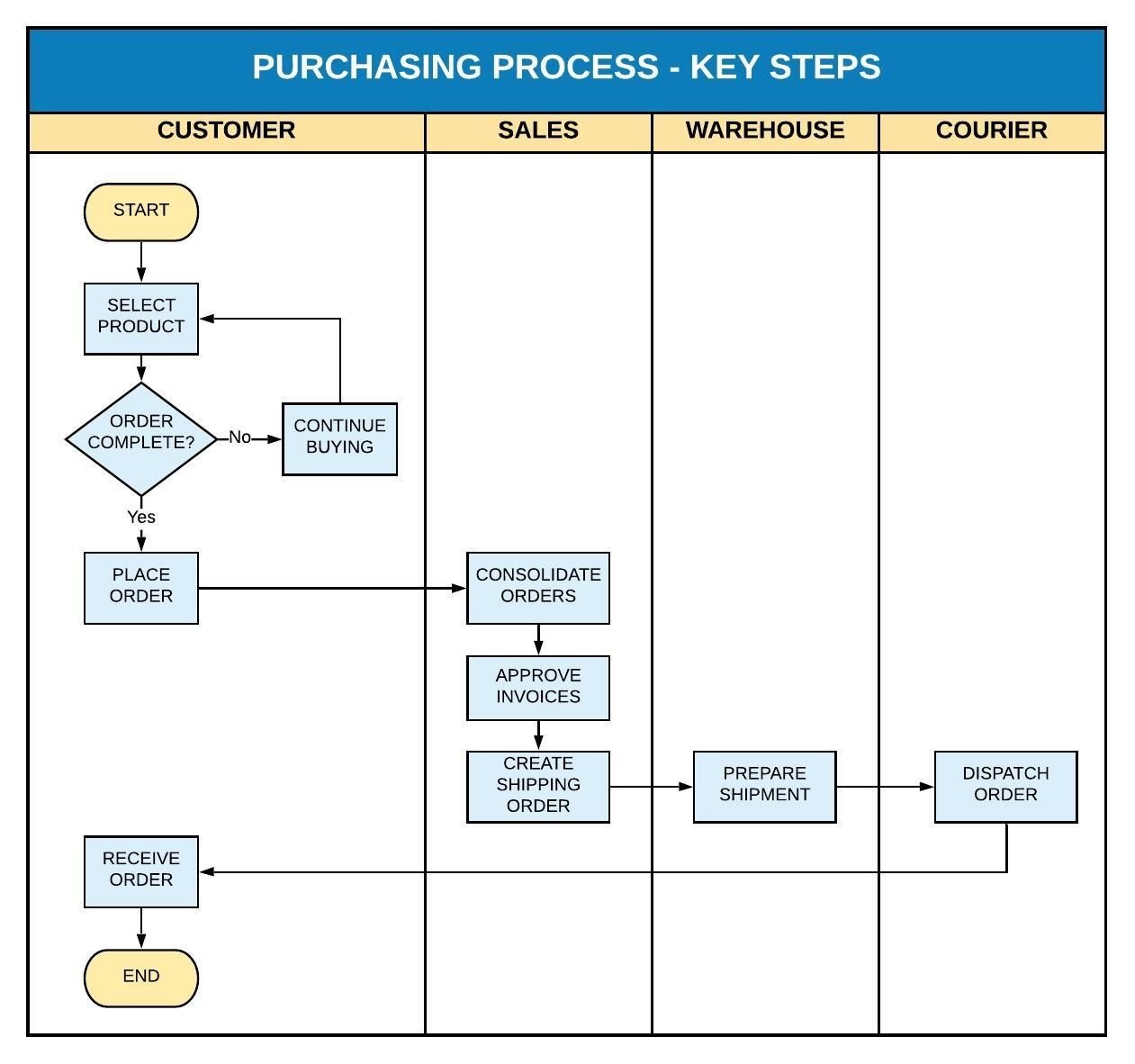
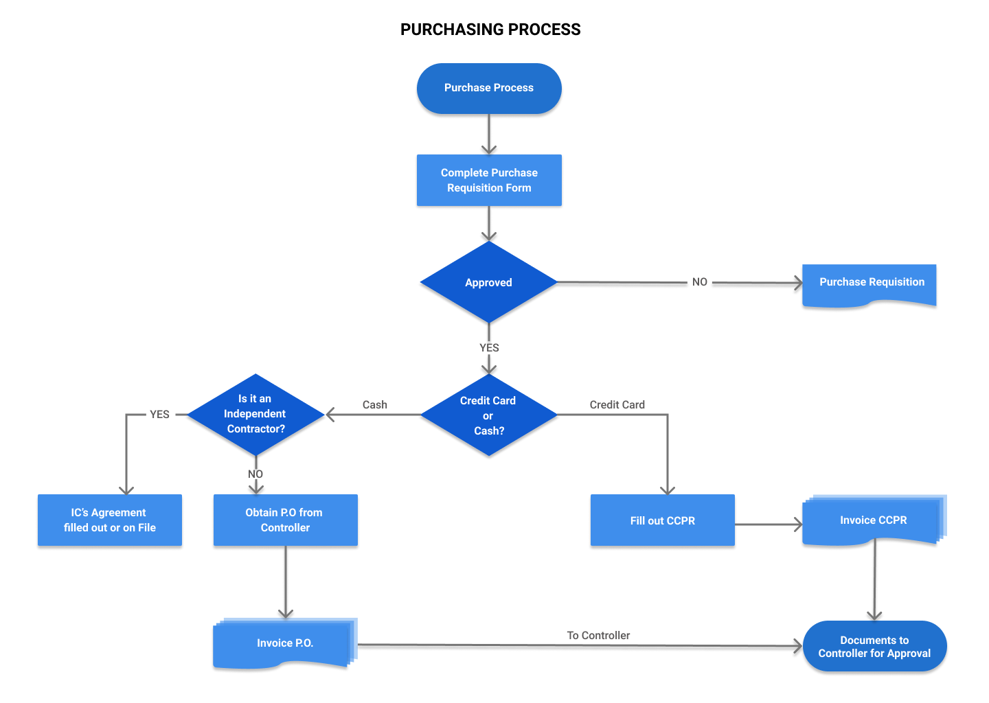
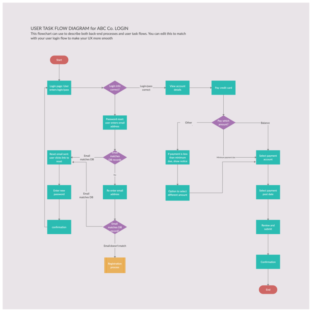
Creating a PFD involves careful analysis and documentation of each step in the process. This includes identifying inputs, outputs, and intermediate stages, as well as any decision points or feedback loops. By capturing this information in a structured manner, a PFD helps to identify inefficiencies, optimize operations, and improve overall performance.
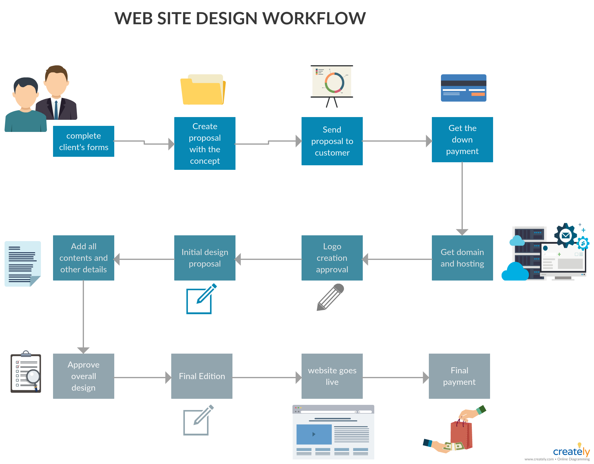
In conclusion, a process flow diagram is an invaluable tool for analyzing and optimizing complex processes. It provides a visual representation of the sequence of steps, facilitating effective communication and collaboration. With its ability to simplify and clarify complex systems, a PFD is essential for enhancing efficiency and productivity in various industries.